


82
5 Programming: Tools
5.4 Three-Dimensional Tool
Compensation
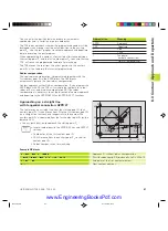
The TNC can carry out a three-dimensional tool compensation (3-D
compensation) for straight-line blocks. Apart from the X, Y and Z
coordinates of the straight-line end point, these blocks must also
contain the components NX, NY and NZ of the surface-normal
vector (see figure below right). The straight-line end point and the
surface normal vector are calculated by a CAD system. The 3-D
compensation enables you to use tools that have other dimensions
than the ones you originally programmed.
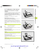
Tool shapes
The available tool shapes (see the upper two illustrations at right)
are defined by the tool radii R and R2:
TOOL RADIUS: R
Distance from the tool center to the tool circumference
TOOL RADIUS 2: R2
Radius of the curvature between tool tip and tool circumference.
The ratio of R to R2 determines the shape of the tool:
R2 = 0
End mill
R2 = R
Toroid cutter
0 < R2 < R
Spherical cutter
These data also specify the coordinates of the tool datum P
T
.
You enter the values for TOOL RADIUS and TOOL RADIUS 2 in the
tool table.
Surface-normal vectors
Definition of surface-normal vectors
A surface-normal vector is a mathematical quantity with
■
a magnitude
here: the distance between the workpiece surface and the tool
datum P
T
, and
■
a direction
End mill and radius mill: perpendicular to the workpiece surface
to be machined, toward the tool datum P
T
Toroid cutter: through P
T
‘ or P
T,
respectively.
The magnitude and direction of a surface-normal vector is
determined by the components NX, NY and NZ.
5
.4
Thr
ee-Dim
ensional T
ool Compensation
P
T
R
R
R
R2
P
T
P
T
R2
P
T
'
Z
Y
X
P
T
NZ
P
NX
NY
Fkap5.pm6
30.06.2006, 07:03
82
www.EngineeringBooksPdf.com
Содержание TNC 426 B
Страница 3: ...BAUSKLA PM6 30 06 2006 07 03 2 www EngineeringBooksPdf com ...
Страница 4: ...BAUSKLA PM6 30 06 2006 07 03 3 www EngineeringBooksPdf com ...
Страница 6: ...CINHALT PM6 30 06 2006 07 03 2 www EngineeringBooksPdf com ...
Страница 16: ...CINHALT PM6 30 06 2006 07 03 12 www EngineeringBooksPdf com ...
Страница 17: ...Introduction 1 Dkap1 pm6 30 06 2006 07 03 1 www EngineeringBooksPdf com ...
Страница 29: ...Manual Operation and Setup 2 Dkap2_3 pm6 30 06 2006 07 03 13 www EngineeringBooksPdf com ...
Страница 39: ...Positioning with Manual Data Input MDI 3 Dkap2_3 pm6 30 06 2006 07 03 23 www EngineeringBooksPdf com ...
Страница 83: ...Programming Tools 5 Fkap5 pm6 30 06 2006 07 03 67 www EngineeringBooksPdf com ...
Страница 106: ...Fkap5 pm6 30 06 2006 07 03 90 www EngineeringBooksPdf com ...
Страница 107: ...Programming Programming Contours 6 Gkap6 pm6 30 06 2006 07 04 91 www EngineeringBooksPdf com ...
Страница 148: ...Programming Miscellaneous functions 7 Hkap7 pm6 30 06 2006 07 03 133 www EngineeringBooksPdf com ...
Страница 165: ...Hkap7 pm6 30 06 2006 07 03 150 www EngineeringBooksPdf com ...
Страница 166: ...Programming Cycles 8 kkap8 pm6 30 06 2006 07 03 151 www EngineeringBooksPdf com ...
Страница 253: ...kkap8 pm6 30 06 2006 07 04 238 www EngineeringBooksPdf com ...
Страница 254: ...Programming Subprograms and Program Section Repeats 9 LKAP9 PM6 30 06 2006 07 04 239 www EngineeringBooksPdf com ...
Страница 265: ...LKAP9 PM6 30 06 2006 07 04 250 www EngineeringBooksPdf com ...
Страница 266: ...Programming Q Parameters 10 MKAP10 PM6 30 06 2006 07 04 251 www EngineeringBooksPdf com ...
Страница 297: ...MKAP10 PM6 30 06 2006 07 04 282 www EngineeringBooksPdf com ...
Страница 298: ...Test Run and Program Run 11 NKAP11 PM6 30 06 2006 07 04 283 www EngineeringBooksPdf com ...
Страница 312: ...MOD Functions 12 Okap12 pm6 30 06 2006 07 04 297 www EngineeringBooksPdf com ...
Страница 332: ...Tables and Overviews 13 Pkap13 pm6 30 06 2006 07 04 317 www EngineeringBooksPdf com ...