6
500
200
300
350
1
2
3
4
5
6
7
8
400
450
500
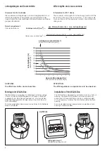
Leitungslänge [m]
cable length [m]
Gesamt-Strombedarf [A]
total power requirement [A]
Leitungsquerschnitt [mm²]
cable cross-section [mm²]
6
2 x 2,5
0
50
100
150
200
4
1,5
2,5
250
+
HAUTAU
LT
Leitungslängen und Querschnitte
Wire lengths and cross-sections
Berechnungsformel:
Calculation formula:
Kabelquerschnitt [mm2] =
ges. Stromaufnahme [A] x max. Leitungslänge [m]
73
Cable cross-section [mm2] =
total current consumption [A] x max. wire lengths [m]
73
Hinweise für 24 V Antriebe
Die maximalen Leitungslängen von der Energiequelle bis zur
letzten Abzweigdose sind gemäß den verwendeten Ader-
querschnitten und der maximalen Stromaufnahme je Antriebs-
gruppe einzuhalten.
ACHTUNG:
Die VDE-Vorschriften sind zu beachten.
Information for 24 V drives
The maximum wire lengths from the energy source until the
last junction box are to be observed acc. to the used cable
cross- sections and the maximum current consumption per
drive group.
ATTENTION:
The VDE regulations or equivalent are to be observed.
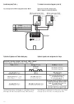
optional
Lüftungstaster LT
Ventilation pushbutton LT
Installation of the WLAN-Box
The WLAN-Box is designed for installation in an on-site flush
housing. The place of installation has to be dry and easy
accessible. An inspection flap or similar is recommended.
It is not necessary to fasten the WLAN-Box within the flush
housing.
For an extended terminal compartment an electronic flush
housing is recommended.
Montage der WLAN-Box
Die WLAN-Box ist ausgelegt zur Montage in eine bauseitige
Unter-Putz-Dose. Der Montageort muss trocken und leicht
zugänglich sein. Eine Revisionsklappe o.ä. ist zu empfehlen.
Eine Befestigung der WLAN-Box in der Unter-Putz-Dose ist
nicht notwendig.
Für einen erweiterten Klemmraum ist eine Unter-Putz- Elektronik-
dose zu empfehlen.


