21
4000429690
E 11.15
US / GB
OPTIMUM 8 - OPTIMUM 1931 E
C
- Familiarization
1.2 -
M
AINTENANCE
SUPPORT
Marking
Description
Marking
Description
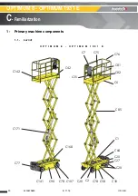
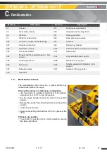
C1
Chassis
C77
Platform access ladder
C2
Front drive wheels
C78
Compartment locking latch
C6
Platform
C81
Sliding guardrail
C7
Platform control box
C82
Deck extension handle
C20
Tie-down (and/or forklift loading)
C85
Scissors
C27
Ground control box
C90
Battery bay (block)
C30
Hydraulic oil tank
C107
Pull T-handle for emergency lowering
C35
Document holder
C141
Rear wheel
C42
'Enable Switch' pedal (Optional - Not
shown)
C142
Lanyard attachment points
C58
Pothole protection
C168
Maintenance support
C64
Tilt sensor
C169
Folding guardrails (Optional - Not
shown)
C75
Extension desk
C171
Scissors lifting cylinder
C76
Guardrail
The maintenance stand must be in place before any
maintenance operation is begun.
Placing the machine in maintenance configuration :
• Lift scissor arms to a sufficient height (floor of the platform
at around 2,5 m / 8 ft 2 in from the ground).
• Pull the plastic handle and put the stand in the vertical
position.
• Release the handle. The stand should remain in the vertical
position.
• Lower the scissor arms.
• Scissor arm pivoting rod should rest on the V groove of the
stand.
Putting in use position :
• To put back the machine into its normal operation, reverse
the steps used above.
Содержание OPTIMUM 1931 E
Страница 2: ...2 4000429690 E 11 15 US GB OPTIMUM 8 OPTIMUM 1931 E...
Страница 10: ...10 4000429690 E 11 15 US GB OPTIMUM 8 OPTIMUM 1931 E A Preface Foreword Notes...
Страница 19: ...19 4000429690 E 11 15 US GB OPTIMUM 8 OPTIMUM 1931 E C Familiarization Familiarization Notes...
Страница 50: ...50 4000429690 E 11 15 US GB OPTIMUM 8 OPTIMUM 1931 E D Inspection and maintenance schedule Notes...
Страница 54: ...54 4000429690 E 11 15 US GB General data Structural part inspection MS0001 Notes...
Страница 64: ...64 4000429690 E 11 15 US GB General data Breaking test procedure MS0004 Notes...
Страница 72: ...72 4000429690 E 11 15 US GB Electric Electrical wiring MS0025 Notes...
Страница 76: ...76 4000429690 E 11 15 US GB Scissor arm Scissor arms screw Periodical checks MS0073 Notes...
Страница 88: ...88 4000429690 E 11 15 US GB Platform Removal replacement of platform assembly MS0095 Notes...
Страница 98: ...98 4000429690 E 11 15 US GB Scissors Removal replacement of Scissor pack MS0096 Notes...
Страница 102: ...102 4000429690 E 11 15 US GB Chassis Calibration steering MS0097 Notes...
Страница 116: ...116 4000429690 E 11 15 US GB Ground control box HAULOTTE Activ Screen MS0106 Notes...
Страница 134: ...134 4000429690 E 11 15 US GB OPTIMUM 8 OPTIMUM 1931 E E Trouble shooting and diagram 3 Electric diagram...
Страница 135: ...135 4000429690 E 11 15 US GB OPTIMUM 8 OPTIMUM 1931 E E Trouble shooting and diagram...
Страница 136: ...136 4000429690 E 11 15 US GB OPTIMUM 8 OPTIMUM 1931 E E Trouble shooting and diagram...
Страница 137: ...137 4000429690 E 11 15 US GB OPTIMUM 8 OPTIMUM 1931 E E Trouble shooting and diagram 4 Hydraulic diagram...
Страница 138: ...138 4000429690 E 11 15 US GB OPTIMUM 8 OPTIMUM 1931 E E Trouble shooting and diagram Notes...
Страница 148: ...148 4000429690 E 11 15 US GB OPTIMUM 8 OPTIMUM 1931 E F Records...


