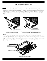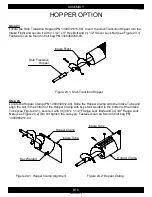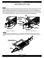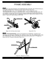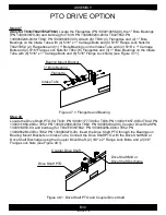
Figure 23.1: Stub Transition Hopper
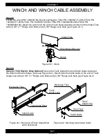
Figure 24.1: Hopper Clamp Alignment
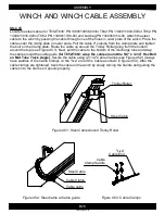
Figure 24.2: Hopper Clamp
B15
ASSEMBLY
1300060439-46-00
HOPPER OPTION
Step 23
Locate the Stub Transition Hopper (PN 1300012615-00). Insert the Stub Transition Hopper into the
Intake Flight and secure it with (1) 1/2" x 3" Hex Bolt and (1) 1/2" Stover Lock Nut (see Figure 23.1).
Fasteners can be found in bolt bag PN 1300060250-00.
Step 24
Locate the Hopper Clamp (PN 1300030912-00). Slide the Hopper Clamp onto the Intake Tube and
align the slot in the bottom of the Hopper Clamp with key stock welded to the bottom of the Intake
Tube (see Figure 24.1), secure it with (4) 3/8" x 1-1/2" Flange Lock Bolts and (4) 3/8" Flange Lock
Nuts (see Figure 24.2) (Do not tighten the nuts yet). Fasteners can be found in bolt bag PN
1300060251-00.
Intake Tube
Key Welded
Hopper Clamp
Intake Tube
Hopper Clamp
Stub Transition
Hopper
Intake Flight
Содержание T8 SERIES
Страница 49: ...C1 PARTS 1300060439 11 00 FRAME T832 1 2 3 2 4 5 6 7 8 9 9 1 10 1 11 10 12 13 14 15 16 1 10 12 17 14 ...
Страница 71: ...C23 PARTS 1300060439 74 00 WINCH CABLE ASSEMBLY T8 1 2 ...
Страница 75: ...C27 PARTS 1300060439 07 00 DISCHARGE HEAD T852 1 2 3 4 5 6 7 4 8 9 10 11 12 13 14 15 6 16 15 17 18 19 20 21 22 ...
Страница 77: ...C29 PARTS 1300060439 08 00 DISCHARGE HEAD T862 1 2 3 4 5 6 7 4 8 9 10 11 12 14 15 6 16 15 17 18 19 20 21 22 13 ...
Страница 79: ...C31 PARTS 1300060439 75 00 FORK T8 1 2 8 3 9 10 10 11 5 7 6 4 ...


