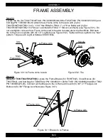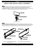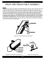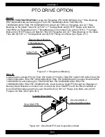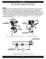
Figure 54.3: Electric Drive Gearbox Mount Location
Figure 54.1: Gearbox and Gearbox Mount
Figure 54.2: Band Clamp
B34
ASSEMBLY
1300060439-82-00
ELECTRIC DRIVE OPTION
Step 54
Locate the Gearbox (PN 1300030176-00), Gearbox Mount (PN 1300032048-00), Band Clamp (PN
1300013280-00), and bolt bag PN 1300060231-00. Mount the Gearbox onto the Gearbox Mount
Bracket with (4) 1/2" X 1" Hex Bolts and (4) 1/2" Lock Washers (see Figure 54.1)
(Orient the
gearbox so the shorter spline shaft stays in left side of the Gearbox Mount)
. Place the Gearbox
Assembly on the Intake Tube and attach the Band Clamp at the bottom of the Gearbox Mount with (4)
3/8" x 2" Flange Lock Bolts and (4) 3/8" Nylon Lock Nuts (see Figure 54.2). Do not tighten the bolts,
Gearbox Assembly might need to move a bit to connect the gearbox with the Drive Shaft. Location of
the Gearbox Mount and Band Clamp varies for the different size of augers, for the approximate
location see Figures 54.3.
Main Frame
Mount Bracket
T832: 10"
T836: 1"
T842: 2'6"
T852: 1'10"
T862: 1"
Gearbox Mount
Gearbox
Gearbox
Mount
Longer
Spline Shaft
Shorter
Spline Shaft
Gearbox
Assembly
Band Clamp
Содержание T8 SERIES
Страница 49: ...C1 PARTS 1300060439 11 00 FRAME T832 1 2 3 2 4 5 6 7 8 9 9 1 10 1 11 10 12 13 14 15 16 1 10 12 17 14 ...
Страница 71: ...C23 PARTS 1300060439 74 00 WINCH CABLE ASSEMBLY T8 1 2 ...
Страница 75: ...C27 PARTS 1300060439 07 00 DISCHARGE HEAD T852 1 2 3 4 5 6 7 4 8 9 10 11 12 13 14 15 6 16 15 17 18 19 20 21 22 ...
Страница 77: ...C29 PARTS 1300060439 08 00 DISCHARGE HEAD T862 1 2 3 4 5 6 7 4 8 9 10 11 12 14 15 6 16 15 17 18 19 20 21 22 13 ...
Страница 79: ...C31 PARTS 1300060439 75 00 FORK T8 1 2 8 3 9 10 10 11 5 7 6 4 ...


