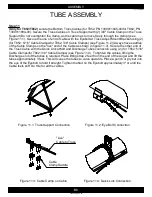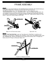
Figure 10.1: Eyebolts to Right and Left
Truss Cable Mount Brackets
*Drive Shaft not shown for clarity
Figure 10.3: Quick Links to Right and Left
Truss Cable Mount Brackets
*Drive Shaft not shown for clarity
Figure 10.4: Quick Links to Discharge End
*Drive Shaft not shown for clarity
Figure 10.2: Eyebolts to
Truss Adjust Mount Bracket
Figure 10.1: Eyebolts to Right and Left
Figure 10.3: Quick Links to Right and Left
Figure 10.4: Quick Links to Discharge End
Figure 10.2: Eyebolts to
B7
ASSEMBLY
1300060439-39-00
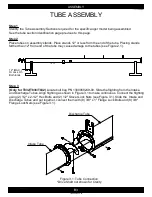
TUBE ASSEMBLY
Step 10
(Only for T852/T862)
Attach (2) 1/2" x 6-1/4" Eyebolts, and (4) 1/2" Hex Lock Nuts to the Left and
Right Truss Cable Mount Brackets on the Intake and Mid Tube connection (see Figure 10.1) (Do not
tighten the bolts right now). Attach (2) 1/2" x 6-1/4" Eyebolts, and (4) 1/2" Hex Lock Nuts to the Truss
Adjust Mount Brackets (see Figure 10.2). Attach (2) the Quick Links to the both side of discharge end
of the Discharge Tube (see Figure 10.3). Attach (2) the Quick Links to the Left and Right Truss Cable
Mount Brackets on the Intake and Mid Tube connection (see Figure 10.4).
Intake Tube
Mid Tube
Mid Tube
Discharge Tube
Discharge End
Truss Adjust
Mount Bracket
Содержание T8 SERIES
Страница 49: ...C1 PARTS 1300060439 11 00 FRAME T832 1 2 3 2 4 5 6 7 8 9 9 1 10 1 11 10 12 13 14 15 16 1 10 12 17 14 ...
Страница 71: ...C23 PARTS 1300060439 74 00 WINCH CABLE ASSEMBLY T8 1 2 ...
Страница 75: ...C27 PARTS 1300060439 07 00 DISCHARGE HEAD T852 1 2 3 4 5 6 7 4 8 9 10 11 12 13 14 15 6 16 15 17 18 19 20 21 22 ...
Страница 77: ...C29 PARTS 1300060439 08 00 DISCHARGE HEAD T862 1 2 3 4 5 6 7 4 8 9 10 11 12 14 15 6 16 15 17 18 19 20 21 22 13 ...
Страница 79: ...C31 PARTS 1300060439 75 00 FORK T8 1 2 8 3 9 10 10 11 5 7 6 4 ...


