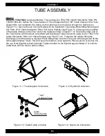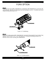
Figure 3.1: Tube Connection
*Drive Shaft not shown for Clarity
B3
ASSEMBLY
1300060439-35-00
TUBE ASSEMBLY
Step 1
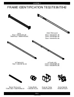
Identify the Tube Assembly Sections required for the specific auger model being assembled.
See the tube section identification page previous to this page.
Step 3
(Only for T832/T836/T842)
Locate bolt bag PN 1300060249-00. Slide the flighting from the Intake
and Discharge Tubes. Align flighting as shown in Figure 3.1 to make continuous. Connect the flighting
using (2) 1/2" x 2-1/2" Hex Bolts and (2) 1/2" Stover Lock Nuts (see Figure 3.1). Slide the Intake and
Discharge Tubes and put together, connect them with (8) 3/8" x 1" Flange Lock Bolts and (8) 3/8"
Flange Lock Nuts (see Figure 3.1).
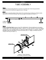
Step 2
Place tubes on assembly stands. Place stands 12" or less from the end of the tube. Placing stands
farther than 12" from end of the tube may cause damage to the tubes (see Figure 2.1).
Intake Tube
Discharge Tube
12" (MAX.)
Or Less On
Both Ends
Содержание T8 SERIES
Страница 49: ...C1 PARTS 1300060439 11 00 FRAME T832 1 2 3 2 4 5 6 7 8 9 9 1 10 1 11 10 12 13 14 15 16 1 10 12 17 14 ...
Страница 71: ...C23 PARTS 1300060439 74 00 WINCH CABLE ASSEMBLY T8 1 2 ...
Страница 75: ...C27 PARTS 1300060439 07 00 DISCHARGE HEAD T852 1 2 3 4 5 6 7 4 8 9 10 11 12 13 14 15 6 16 15 17 18 19 20 21 22 ...
Страница 77: ...C29 PARTS 1300060439 08 00 DISCHARGE HEAD T862 1 2 3 4 5 6 7 4 8 9 10 11 12 14 15 6 16 15 17 18 19 20 21 22 13 ...
Страница 79: ...C31 PARTS 1300060439 75 00 FORK T8 1 2 8 3 9 10 10 11 5 7 6 4 ...


