background image

3

Publication  5419-013 REV1.0

Safety Information

Please read the following safety precautions to ensure proper use 

of your syringe pump. If the equipment is used in a manner not 

specified, the protection provided by the equipment may  

be impaired. 

To Prevent Hazard or Injury: 

USE PROPER POWER SUPPLY

The pump is supplied with an approved power supply and line cord. 

To maintain the safety and integrity of the device, use only the 

following recommended power supplies.

Globtek Inc.

Model: GTM96600-6048-18-T3

GTM21097-5048-18

Output: 30V DC 2.0 A

30V DC 1.66 A

Input:

100-240V~, 50/60 Hz, 1.5 A 100-240V~, 50/60 Hz, 1.6 A

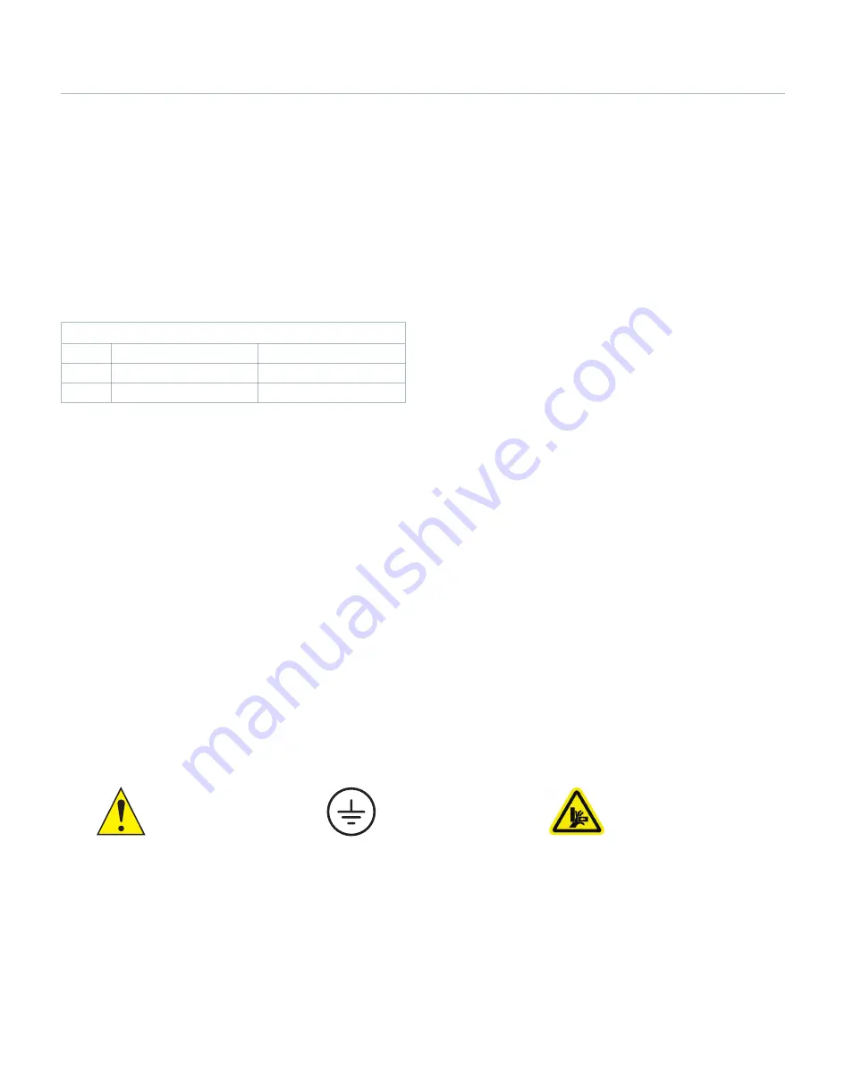
CAUTION

Refer to Manual

Protective 

Ground Terminal

CAUTION:  

Avoid Pinch Hazard

USE PROPER LINE CORD

Use only the specified line cord and power supply for this product 

and make sure line cord is certified for country of use. The operating 

voltage range for the Pump 33 DDS is 100-240 VAC, 50-60 Hz. 


GROUND THE PRODUCT

This product is grounded through the grounding conductor of the 

power cord. To avoid electric shock, the grounding conductor must 

be connected to earth ground. Before making any connections to the 

input or output terminals of the product, ensure that the product is 

properly grounded. 


MAKE PROPER CONNECTIONS

Make sure all connections are made properly and securely. Any signal 

wire connections to the unit must be no longer than 3 meters (except 

RS485 pump-to-pump communication cable). 


OBSERVE ALL TERMINAL RATINGS

Review the operating manual to learn the ratings on all connections. 


AVOID EXPOSED CIRCUITRY

Do not touch any electronic circuitry inside of the product. 


AVOID PINCH HAZARD

A pinch hazard may exist between the pusher block and end blocks. 

Avoid placing fingers between these points while the pump is 

running. 


DO NOT OPERATE WITH SUSPECTED FAILURES

If damage is suspected on or to the product do not operate the 

product. Contact qualified service personnel to perform inspection. 


ORIENT THE EQUIPMENT PROPERLY

Do not orient the equipment so that it is difficult to manage the 

connection and disconnection of devices. 


PLACE PRODUCT IN PROPER ENVIRONMENT

Do not use the equipment in an explosive environment. 


OBSERVE ALL WARNING LABELS ON PRODUCT

Read all labels on product to ensure proper usage.

Содержание Pump 33 DDS

Страница 1: ...Publication 5419 013 REV1 0 Pump 33 DDS 70 3333 Pump 33 DDS Dual Drive System User s Manual ...

Страница 2: ...in Condition Setup 24 Twin Condition Run 28 Settings 29 Screen Lock Fast Forward Fast Reverse 29 Settings Menu 29 Pump Information 29 Setting Time Date 30 Screen Backlight Adjustment 30 Pump Address 31 Password 31 Baud Rate 32 Force Setting 33 Alarms 33 SUBJECT PAGE External Connections 33 37 USB Pinout 33 USB Virtual Commport Driver Installation 34 Upgrade Software 36 RS 232 Pinout 38 RS 485 Pino...

Страница 3: ...n the two year warranty period promptly contact Harvard Apparatus 84 October Hill Road Holliston Massachusetts 01746 using our toll free number 1 800 272 2775 or outside the U S call 508 893 8999 Our E mail address is support hbiosci com Goods will not be accepted for return unless an RMA returned materials authorization number has been issued by our customer service department The customer is res...

Страница 4: ...ctric shock the grounding conductor must be connected to earth ground Before making any connections to the input or output terminals of the product ensure that the product is properly grounded MAKE PROPER CONNECTIONS Make sure all connections are made properly and securely Any signal wire connections to the unit must be no longer than 3 meters except RS485 pump to pump communication cable OBSERVE ...

Страница 5: ...procating Condition In Reciprocating Condition the syringe channels move in opposite directions at the same rate using the same syringe size and type When combined with a valve box the reciprocating condition can provide the continuous fluidic delivery of a peristaltic pump with the accurate pulseless low flow rates provided by a syringe pump Twin Condition The Twin Condition allows both syringes ...

Страница 6: ...rrel connector into the DC Input on the rear of the unit 3 Turn on the main power switch located on the rear panel 4 The Pump 33 DDS touch screen display will illuminate and display the startup screen while performing self diagnostics When complete the unit will display either the Condition Select Condition Setup or Condition Run screen depending on the configuration during the last use of the pum...

Страница 7: ... all settings Pump Command Control ASCII Command Set Real time Clock Yes with battery backup battery included and required for real time clock Connectors Power Barrel connector barrel post 2mm X 5mm male plug RS 485 IEEE 1394 6 position USB Type B RS 232 9 pin D Sub Connector I O TTL 15 pin D sub connector one for each axis Footswitch Connections Mini phono jack Drive Motor Two independent stepper...

Страница 8: ...ting Humidity The following is a chart of operating humidity versus temperature for the Pump 33 DDS Please note as operating temperature increases the maximum allowable operating humidity decreases Operating Humidity vs Temperature Chart ...

Страница 9: ...mp Channel 1 P1 End Block P2 End Block P1 Lead Screw P1 Touch Screen Knob for Pusher Block P1 Lead Screw Release Knob for Pusher Block P2 Lead Screw Release Pusher Block P2 Lead Screw P2 Guide Rods P2 Syringe Clamp Syringe Holder Block P2 Syringe Clamp Syringe Holder Block P1 Pusher Block P1 Guide Rods P1 1 Syringe Plunger Retaining Bracket Retaining Bracket Tightening Thumbscrews 14 Clamp Collars...

Страница 10: ... Condition Setup section of this manual 4 Place the Syringe Barrel 13 on the Syringe Holder Block 5 and move the Pusher Block 2 to accommodate the plunger 5 Make sure the Syringe Barrel Flange 12 and the Syringe Plunger Flange 10 are held by the Retaining Brackets 1 9 6 Press the Retaining Brackets firmly against the flanges and tighten with the Tightening Thumbscrews 1 9 7 Place the Syringe Clamp...

Страница 11: ... each condition based on the features that condition supports When you first turn on the unit after delivery from the Harvard Apparatus factory the following start up screen will briefly appear Then the unit will display the Condition Select Screen If the Condition Select screen does not appear please press the back button see Independent Condition below until you enter the Condition Select Screen...

Страница 12: ... Run Stop Pump Channel 2 P2 Starts Stops Pump Channel 2 P2 Only in Independent Condition Run Stop Pump Channel 1 2 P1 P2 Starts Stops both Pump Channel 1 P1 and Pump Channel 2 P2 Return to Previous Screen Returns the user to the previous screen System Settings Enters System Settings Menu to adjust Time Date Backlight Pump Address Baud Rate Password Force Alarm Pump Information and Upgrade Software...

Страница 13: ...user to the Run Screen Accept Used to accept the parameters settings on a screen and advance to the next menu Cancel Used to cancel any changes entries on a screen in the menu Reset Counters Pump Channel 1 P1 Clears the counter timers for Pump Channel 1 P1 for Independent Condition Only Reset Counters Pump Channel 2 P2 Clears the counter timers for Pump Channel 2 P2 for Independent Condition Only ...

Страница 14: ...different syringe types size force target volume or time and flow rate settings This innovative condition allows you to run two different flows at the same time using one instrument Select Independent from the Condition Select Screen The Independent Condition Setup Screen will appear There are two sections to each Condition Setup screen The top two thirds of the screen is dedicated to the mode syr...

Страница 15: ...m of the screen contains the Run Fast Forward Fast Reverse and System settings buttons This manual addresses the Run functions after each condition setup section The Settings section of this manual covers the system setting functions The following is a summary of the Independent Condition Setup Screen with detailed explanation of each button function ...

Страница 16: ...an be different Select the desired modes for both P1 and P2 The modes can be set differently while in Independent Condition Once selected the mode button will turn green Press the Green check button in the bottom right hand corner of the screen to accept the Mode selections for P1 and P2 Press the Red X to discard the selections and return to the Independent Condition Setup screen Independent Cond...

Страница 17: ... specified in this manual because some larger syringes may be compatible with the Pump 33 DDS Please contact Technical Support for more information Select Syringe Custom Syringe Screen Custom Syringe Settings Screen Set Rate Screen Infuse Mode Shown 3 RATE SELECT Select the flow rate for Pump Channel 1 Pump Channel 2 Independent Condition requires the user to enter a flow rate for the selected mod...

Страница 18: ... and Withdraw only versus Infuse Withdraw and Withdraw Infuse Set Target Volume Set the Target Volume for Pump Channel 1 Pump Channel 2 Independent Condition requires the user to enter a Target Volume or Time for the selected mode on both P1 P2 On the Independent Condition setup screen press the Target Select button for Pump Channel 1 P1 or Pump Channel 2 P2 The Set Target Volume or Time screen wi...

Страница 19: ...ck Once released the pusher block will stop immediately During operation the Pump 33 DDS will display a red message box showing the pusher block direction The following examples are from the setup screen This same functionality is available in the condition run screens Note Certain buttons are disabled in certain conditions Stall detection is disabled during Fast Forward Fast Reverse operation The...

Страница 20: ...on Setup Pump Channel 1 P1 2 P2 Fast Forward Feature Pump Channel 2 P2 Fast Reverse Feature Pump Channel 1 P1 Fast Reverse Feature Pump Channel 1 P1 2 P2 Fast Reverse Feature Pump Channel 1 P1 Fast Forward Feature Pump Channel 2 P2 Fast Forward Feature ...

Страница 21: ...can start P1 and P2 individually or at the same time This operation can be performed from the setup or run screens Refer to the setup screen button guide shown below defined at the start of this section To start the Pump 33 DDS from the setup screen press the Pump Channel 1 P1 Run Stop button 5 to start P1 only Select the Run Stop button 10 for Pump Channel 2 P2 to start P2 only Select the Run Sto...

Страница 22: ...o start stop both P1 and P2 at the same time 22 RESET COUNTERS PUMP CHANNEL 2 P2 Press to reset the various counters for P2 see 25 23 RUN STOP PUMP CHANNEL 2 P2 Press to start stop P2 24 P2 GRAPHICAL SYRINGE STATUS This graphic provides the current volume in text and in graphical form 25 REALTIME STATUS Displays the set Mode Syringe Time Elapsed and Time Left for the current run Target and Infused...

Страница 23: ... are a Infuse Withdraw The syringe will operate in Infuse Withdraw mode only P1 will infuse first while P2 is withdrawing Facing the Pump 33 DDS the pusher block for the infusing pump channel will push the syringe plunger from left to right at the set flow rate and volume time while infusing and the pusher block for the withdrawing channel will pull the syringe plunger from right to left at the se...

Страница 24: ...he Independent Condition Rate Select section a Infuse Withdraw Mode Rate Select Select the Infuse rate and Withdraw rate The user can set different rates for Infuse and Withdraw b Withdraw Infuse Mode Rate Select Select the Withdraw rate and Infuse rate The user can set different rates for Infuse and Withdraw 4 TARGET SELECT Select the Target Volume depending on the Mode selected Infuse Withdraw o...

Страница 25: ...will pull the syringe plungers from right to left at the set flow rate and volume time c Infuse Withdraw The P1 and P2 syringes will both operate in infuse withdraw mode The volume of the cycle is set in the Target Select selection Facing the Pump 33 DDS the P1 and P2 pusher blocks will push the syringe plungers from left to right and then pull the syringe plungers from right to left at the set fl...

Страница 26: ...Infuse Target Select entry is the same as covered in the Independent Condition Target Select section NOTE Please see below for details on the impact of the Ganging feature on the Rate and Target Select settings a Ganging Feature RATE AND TARGET SELECT The Ganging feature described above impacts the Rate Select setting When the user selects the x2 Gang feature in the Twin Condition Select Syringe t...

Страница 27: ...or both Independent and Reciprocating Condition In Twin Condition the user will select one target volume or time for both P1 and P2 as shown in the screen below The user can set the target flow rate or time time available in Infuse and Withdraw modes only rate for both Twin syringes In the case of a 2 5 ml syringe the available maximum volume is 2 5 ml as shown in the screen below When the user ru...

Страница 28: ...he user will select one rate for both P1 and P2 as shown in the following screen Twin Condition Setup Twin Condition Rate Select for x2 Gang Setting Twin Condition Run Screen for x2 Gang Setting Twin Condition Target Select for x2 Gang Setting Showing 5 ml maximum volume The Target Select screen for the x1 Gang selection will look similar to the Target Select screen for both Independent and Recipr...

Страница 29: ...imilar to both the Independent and Reciprocating Run screens Note The user needs to select and highlight both P1 and P2 to move both P1 and P2 pusher blocks at the same time using the Fast Forward and Fast Reverse buttons Please see below for a summary of the Twin Condition Run screen ...

Страница 30: ... section describes the options available in this Settings screen of the application software Select the settings button from either the Condition Select Condition Setup or Condition Run screen Settings Menu Screen The Pump 33 DDS monitors usage and provides convenient reminders for periodic maintenance or calibration Harvard Apparatus recommends that the user perform system calibration checks adju...

Страница 31: ...Units button 2 To change the Time select the Time button and enter the current time in hh mm ss hours minutes seconds format Select the Time Format button to toggle between AM 24 Hour and PM values for the Time 3 When the Date and Time values are correct choose the Accept button to save your changes and return to the Settings screen Set Date and Time Screen The user can adjust the backlighting lev...

Страница 32: ...mp Address Screen Baud Rate To set the Password go to the Settings screen Press the Set Password button enter your desired password up to 6 digits and press the Accept button Please write your password down and keep it in a secure location For attaching the Pump 33 DDS to an external device using RS 232 serial communications you can easily adjust the baud rate to optimize communications TO ADJUST ...

Страница 33: ...ifferent force for Pump Channel 1 P1 and Pump Channel 2 P2 Reciprocating and Twin Conditions only require allow one force setting for both Pump Channel 1 P1 and Pump Channel 2 P2 2 When you have selected or entered the desired force value choose Accept to return to the Settings menu Force Setting Force Settings Screens for Reciprocating Condition Force Settings Screens for Independent Condition Fo...

Страница 34: ...ones which are played at powerup System Alarms Other system alarms indicating unexpected operation Mute All Selecting this option mutes all audible alarms The Pump 33 DDS pump incorporates an Audible Alarm feature to warn the operator about various operating conditions errors and power outages The following alarms are user configurable in the Settings section of the application When selected the a...

Страница 35: ...n the media CD provided with the shipment of the Pump 33 DDS The Pump 33 DDS driver package is compatible with Windows XP 7 8 1 10 32 and 64 bit systems The driver installation procedure may differ based on the version of Windows the user employs The following installation instructions were created on a PC running Windows 7 1 Connect the Pump 33 DDS to the Windows computer via USB Run the file HBI...

Страница 36: ...may prompt you to authorize the installation of the driver Enable the check box to the left of the text Always trust software from Harvard Bioscience and click the Install button 4 Once the Pump 33 DDS Windows driver installs click the Finish button to close the installer ...

Страница 37: ...p to the PC on which Firmware Updater is installed and file s containing the updated application s These files will have a file type of srec The general process for software update is 1 Copy the latest software version to your desktop format is filename srec 2 Disconnect all I O devices and then connect the pump to a PC using a USB cable 3 On the pump press the Settings button then press the Upgra...

Страница 38: ...37 Publication 5419 013 REV1 0 7 Click the Start Update button see below 8 After the update is complete press Reboot to power cycle the pump see below External Connections ...

Страница 39: ...S 232 Pinout RS 485 Pinout CAUTION Do not connect to firewire ports on a PC Damage may occur to pump and or PC 1 2 3 4 5 6 7 8 9 Pin Signal 2 RXD 3 TXD 5 GND 1 4 6 9 N C Baud Rates 9600 19200 38400 57600 115200 Word size 8 Parity None Stop Bits 1 Pump PC ...

Страница 40: ...stops on rising edge 4 Trigger 1 Output TTL Logic Output Default Low Control thru method or serial comm 5 Trigger 2 Output TTL Logic Output Default Low Control thru method or serial comm 6 Sync Output TTL Logic Output Rising Edge Start Infuse Falling Edge Start Refill 7 Trigger 2 Output TTL Logic Output High Refill Low Infuse 8 Valve Output controls voltage only TTL Logic Output High Valve Activat...

Страница 41: ...p is in Poll ON mode an XON character is added after the prompt In the following list of commands The general format of the response is lf addr prompt unless otherwise noted The addr field of the general response format will show the address of the responding pump it will be included if and only if the command was addressed to a pump other than the one which is connected to the USB cable Many comm...

Страница 42: ...format address sp 0 99 Query response to address lf addr address lf addr prompt Query response to address new addr lf addr prompt Examples address address sp 0 BAUD Sets or displays the RS232 port baud rate Valid baud rates are 9600 19200 38400 57600 115200 128000 230400 256000 460800 and 921600 Note that some computers may not be able to handle baud rates above 115200 Command format baud sp 9600 ...

Страница 43: ...ent lf addr prompt Query response to cond new condition lf addr prompt Example condition condition sp T condition sp Independent CONFIG Sets or displays the pump configuration In response to this command the pump will display a list of mechanical configuration variables and their current settings Except in instances of custom configurations these values are not expected to require changes Command ...

Страница 44: ...ent Condition ftswitch sp a b ab sp m r f Query response the first line will be repeated for each requested axis lf addr axis sp Momentary lf addr prompt or lf addr axis sp Active high lf addr prompt or lf addr axis sp Active low lf addr prompt Command format Twin or Reciprocating Condition ftswitch sp m r f Query response lf addr sp Momentary lf addr prompt or lf addr sp Active high lf addr promp...

Страница 45: ...te changes to memory is turned on or off accordingly This command should be used when sending commands quickly to avoid damage to the pump memory Command format rsave sp On Off Query response lf addr On Off lf addr prompt Pump Chain Commands TIME Sets or displays the date and time Command format time sp mm dd yy dd mm yy yy mm dd sp hh mm ss Query response lf addr M lf addr prompt The date order f...

Страница 46: ... lines is shown or lf addr Automatic lf addr prompt this line follows the displayed axis info Example valve sp auto VERBOSE Specify the level of detail displayed in error messages When Verbose is set to On full two line error messages will be displayed for errors When Verbose is set to Msg a one line error messages will be displayed for errors When Verbose is set to Off no error messages will be d...

Страница 47: ...lected for axis a or b or show info for both a b for each axis requested lf addr axis lf addr Volume Diameter cr lf addr index sp vol sp ul ml sp diam one line is displayed for each syringe lf addr prompt SYRINGE COMMANDS Command format Independent Condition syr sp a b ab sp code sp index Example 1 syr sp ab Query response to syr sp a b ab Show syringe that has been selected for axis a or b or lis...

Страница 48: ... ab lf addr axis xl cr displays one line per requested axis lf addr prompt displayed after last axis line Query response to svolume sp a b ab sp syringevolume ul ml lf addr prompt Command format Reciprocating or Twin Condition svolume sp syringe volume ul ml Query response to svolume lf addr xl cr lf addr prompt Query response to svolume sp syringevolume ul ml lf addr prompt Examples svolume sp ab...

Страница 49: ... Reciprocating or Twin Condition run Command format Independent Condition stop sp a b ab Command format Reciprocating or Twin Condition stop Command format Independent Condition wrun sp a b ab Command format Reciprocating or Twin Condition wrun CRATE Displays the current rate s at which the motor s is are running A valid response is returned only in dynamic situations while the pump is running NOT...

Страница 50: ... Pump Chain Commands ITRATE Sets or displays the target infusion rates for ramping The rate argument may be replaced with max or min to set the maximum or minimum rate respectively lim may be used to display the range limits Command format Independent Condition itrate sp a b ab sp max min lim rate sp rate units Query response lf addr axis xl xxx displays one line per requested axis lf addr prompt ...

Страница 51: ...sp 10 sp ml min Pump Chain Commands TRATE Sets or displays the target infusion rates for ramping for the current direction for the specified axis It can be used in place of ITRATE if the current direction for the given axis is Infuse or WTRATE if the current direction is Withdraw The rate argument may be replaced with max or min to set the maximum or minimum rate respectively lim may be used to di...

Страница 52: ... if lim argument is used lf addr xl xxx to xl xxx lf addr prompt Example wrate sp 10 sp ml min Pump Chain Commands WTRATE Sets or displays the target withdraw rates for ramping The rate argument may be replaced with max or min to set the rate to the maximum or minimum rate respectively lim may be used to display the range limits Command format Independent Condition wtrate sp a b ab sp max min lim ...

Страница 53: ...d format Reciprocating or Twin Condition ivolume Query response lf addr xl lf addr prompt Pump Chain Commands WVOLUME Displays the withdrawn volume Command format Independent Condition wvolume sp a b ab Query response lf addr axis xl displays one line per requested axis lf addr prompt Command format Reciprocating or Twin Condition wvolume Query response lf addr xl lf addr prompt TVOLUME Sets or di...

Страница 54: ...ayed after last axis line Command format Reciprocating or Twin Condition wtime Query response lf seconds lf prompt or lf lf prompt Command format Independent Condition itime sp a b ab Query response lf addr axis time given in seconds or displays one line per requested axis lf addr axis time in HH MM SS format lf addr prompt displayed after last axis line Command format Reciprocating or Twin Condit...

Страница 55: ... w or W if the pump is withdrawing If the letter is lower case the pump motor is idle If upper case the pump motor is running Flag two Ln is the limit switch status If the infuse limit switch was hit i or I is displayed If the withdraw limit switch was hit w or W is displayed If no limit switch was hit or the pump does not have limit switches is displayed Flag three Sn is the stall status and will...

Страница 56: ...es use a lint free cloth to remove loose dust Use care to avoid scratching the clear display window For more efficient cleaning use a soft cloth dampened not soaked with water an aqueous solution of 75 isopropyl alcohol or a mild detergent Maintenance Maintenance Battery Replacement and Troubleshooting 1 Remove screw and swing cover to the side 2 Slide battery out from under clip 3 Install Lithium...

Страница 57: ...us Valve Box manual Troubleshooting Infusion Accuracy To ensure infusion accuracy always use new syringe s and measure syringe bore diameter and enter actual dimensions in millimeters mm using the Custom Syringe entry option Additionally make sure that the guide rods and lead screw are properly lubricated RS 232 Difficulties Verify that the baud rates data framing parameters data bits parity and s...

Страница 58: ...ter 5 10 3 1 ml long 4 7 mm 20 20 2 1 ml 4 699 mm 10 14 567 1 ml short 6 6 30 23 2 3 8 585 25 23 033 2 5 ml 9 60 29 2 5 11 989 50 32 573 5 13 10 14 427 10 15 8 Size Diameter 20 19 05 20 20 1 1 ml 6 40 mm 30 21 59 Size Diameter 30 23 2 2 5 9 3 50 26 594 10 µl 0 461 mm 50 29 1 5 13 1 60 26 594 25 0 729 10 15 3 50 1 03 20 21 100 1 457 30 23 250 2 304 Size Diameter 50 29 Size Diameter 500 3 256 5 µl 0...

Страница 59: ... 13 83 nl min 14 36 ml min 10 ml 14 43 mm 20 03 nl min 20 8 ml min 20 ml 19 05 mm 34 91 nl min 36 26 ml min 30 ml 21 59 mm 44 84 nl min 46 57 ml min 50 60 ml 26 59 mm 68 02 nl min 70 64 ml min 50 60 ml 29 2 mm 82 03 nl min 85 1 ml min Ordering Information Order Product 70 3333 Pump 33 DDS Dual Drive Syringe Pump Accessories 70 2215 Footswitch with Phono Plug 70 4000 RS 485 Cable for Pump to Pump C...

Страница 60: ...d Holliston Massachusetts 01746 Phone 508 893 8999 Toll Free 800 272 2775 Fax 508 429 5732 E mail support hbiosci com Web www harvardapparatus com Germany Hugo Sachs Elektronik Gruenstrasse 1 March Hugstetten D 79232 Germany Phone 49 0 7665 92 00 0 Fax 49 0 7665 92 00 90 E mail info hugo sachs de Web www hugo sachs de France Harvard Apparatus S A R L 6 Avenue des Andes Miniparc Bat 8 F 91952 Les U...

Отзывы: