MODU-FIRE® Forced Draft Gas-Fired Boiler
10
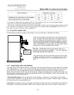
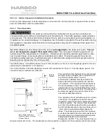
Type of Surface
Dimensions (inches)
A
B
C†
D
CSA Minimum Clearances to Combustibles
24
24*
24
24
Recommended Service Clearances
30
24*
24
24**
† “C" dimension includes clearance to remove the burner. Do not put pipes, ducts, etc. in this area above the boiler.
*CSA minimum. Actual clearance depends upon venting requirements.
** Service access need be only on one side of a boiler or row of boilers. Boilers may be installed immediately adjacent to each
other. However, Harsco Industrial, Patterson-Kelley recommends this clearance between each boiler when there is insuffi-
cient access at the rear to allow for service and adjustment.
3.4 E
LECTRICAL
C
ONNECTIONS
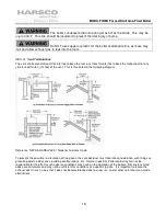
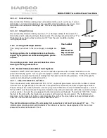
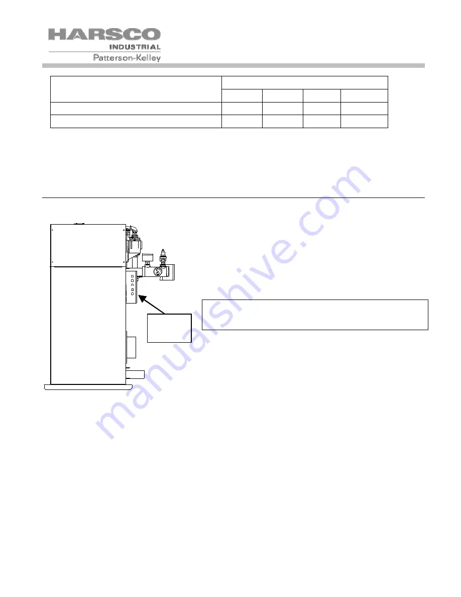
All field wiring connections for power and controls are in the junction box on the back of the boiler.
The boiler wiring label is attached to the inside front door of the
boiler. An external electrical disconnect (not supplied with the
boiler) with adequate overload protection is required. The boiler
must be grounded in accordance with local codes or in the ab-
sence of such requirements, in the U.S. with National Electrical
Codes, ANSI/NFPA No. 70 latest edition and in Canada, wire ac-
cording to the current Canadian Electrical Code.
NOTICE! A dedicated earth ground (green wire) is re-
quired to avoid nuisance shutdowns. It is also important
that proper polarity be maintained.
The junction box at the rear of the boiler contains terminal strips
for power and control connections. A detailed schematic of the
connections is shown in 6.1.7. These connections are as fol-
lows:
3.4.1 High Voltage (HV) Terminal Block
The boiler power circuit requires 240 volts, single phase, 60 hertz, with a dedicated neutral and ground as labeled.
The voltage between L1 (HV-1) and L2 (HV-2) must be approximately 230V, while the voltage from each line to
the neutral (HV-3) must be approximately 120V AC. Electrical service must be rated for 17 amps minimum.
Before starting the boiler, check to ensure that the proper voltage and amperage are connected to the boiler and
that the boiler is connected to a suitable fused disconnect switch or circuit breaker. There must be less than 1.0V
from Neutral (HV-3) to Ground (HV-10)
120VAC Switched Output- This contact closes when the boiler is switched on. This provides 120VAC 5Amp
service to HV12 and HV13. The neutral for this circuit is provided on HV4 and HV5. When the boiler is switched
off, these terminals are switched off as well.
3 Way Valve- This output is normally energized, maintaining the three way valve in the position to provide heat to
the building. The Domestic Hot Water (DHW) call for heat de-energizes this circuit, causing the 3 way valve to
Electrical
Connections
Содержание MODU-FIRE FORCED DRAFT N750
Страница 45: ...MODU FIRE Forced Draft Gas Fired Boiler 45 6 1 5 Main Control Panel Point to Point Left Side Alarm Flame Enable...
Страница 46: ...MODU FIRE Forced Draft Gas Fired Boiler 46 6 1 6 Main Control Panel Point to Point Right Side...
Страница 47: ...MODU FIRE Forced Draft Gas Fired Boiler 47 6 1 7 Junction Box Point to Point and Customer Connections...
Страница 48: ...MODU FIRE Forced Draft Gas Fired Boiler 48 6 1 8 Customer Connections Details...


