MODU-FIRE® Forced Draft Gas-Fired Boiler
18
3.5.3.2.3 Interior Component Installation Clearances
All vent system components shall be installed so as to maintain the vent manufacturer’s required minimum clear-
ances to combustibles and non-combustibles.
3.5.3.3 Flue Connection
The boiler vent should not be connected into any portion of another me-
chanical draft system without consulting the vent manufacturer. This boiler operates under a positive
vent pressure. The boiler shall not be connected to any part of a vent system serving a Category I or
II appliance, nor shall a Category I or II appliance be connected to any part of the vent system serving
this appliance. Improper interconnection of venting systems may result in leakage of flue gases into
occupied spaces.
NOTICE! Make sure that the weight of the vent is not supported by the boiler vent collar. The col-
lar is not designed to support the weight of the vent. The vent system shall be supported in ac-
cordance with the manufacturer’s instructions. Horizontal vent sections shall be supported in a man-
ner to prevent sags or low spots where condensate can collect. Structural supports must be con-
nected to building elements of sufficient strength to withstand the weight of the vent system and any
bending forces imposed by the venting system.
The 750,000 Btu & 1,000,000 Btu boilers have 6” OD connections for the vent. If venting design permits, this con-
nection may be reduced to 4” or 5” diameter.
The 1,500,000 Btu & 2,000,000 Btu boilers have 8” OD connections for the vent. If venting design permits, this
connection may be reduced to 6” diameter.
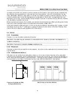
The connection from the boiler to the vent should
be made using an adapter that is designed to fit
the OD of the boiler outlet. The vent
manufacturer’s adapter must be sealed to the
boiler outlet with sealant listed for use with the
vent material. The connection from the boiler to
the vent should be as direct as possible and the
upward slope of any horizontal breaching should
be at least ¼ inch per linear foot. Provisions must
be made for supports to prevent contact of the
vent with combustible surfaces.
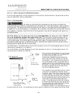
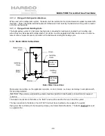
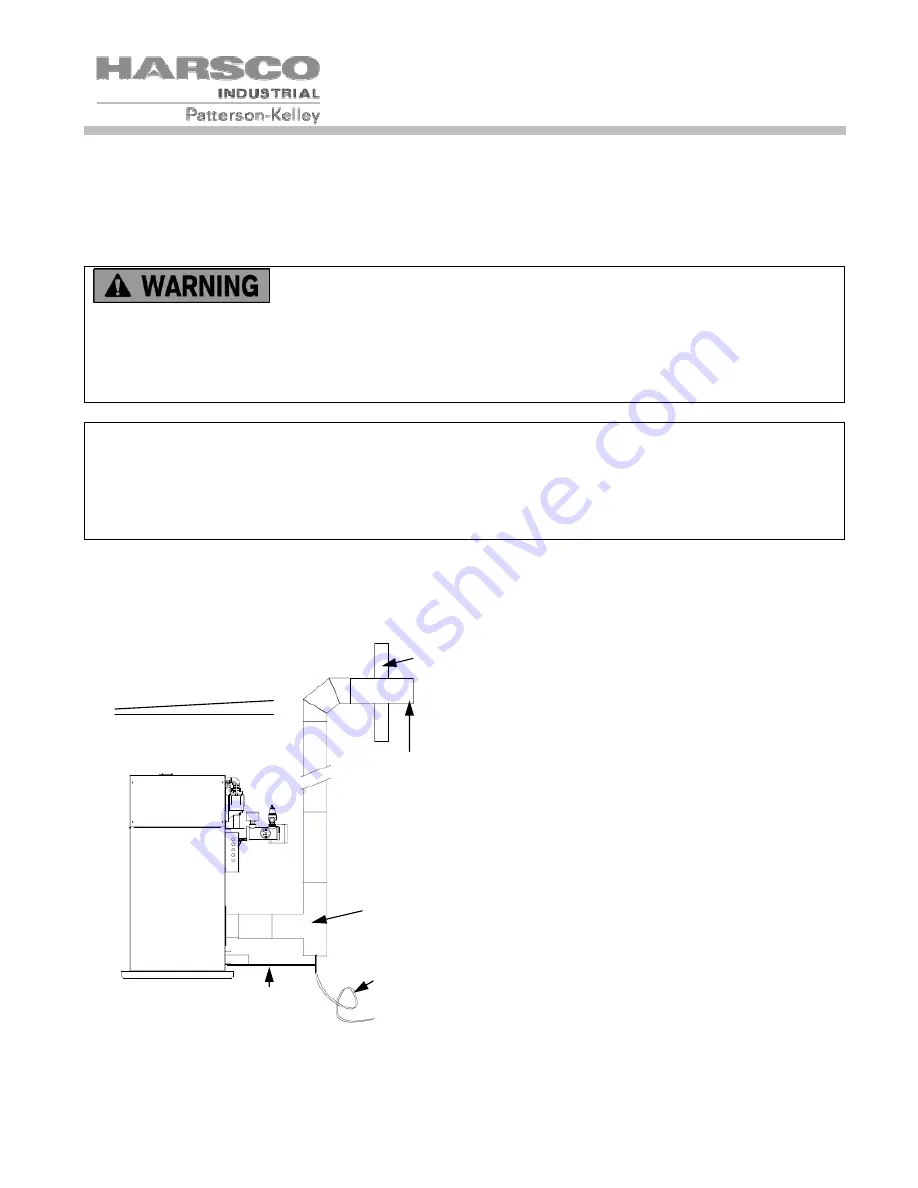
The complete exhaust with drain system is shown
in the figure. The appliance connector should
incorporate provisions to drain condensate formed
in the vent system. The first turn from horizontal
to vertical should be made with either a standard
tee with condensate drain cap or an elbow
with
an
“inline” drain installed immediately above the
elbow. The condensate drain line from the boiler
must be connected to the stack drain upstream of
the stack trap using a material that will withstand
condensate corrosion and a maximum
temperature of 400°F. The stack trap shall have a
minimum height of 4 inches. The condensate must be routed to a suitable drain that complies with all local codes.
Boiler Outlet
Building
Sidewall
See 3.5.3.4 for
termination details
Pitch Towards Boiler
¼” per foot min
Tee
w/Drain
Stack Drain
w/Trap
4” min height
Boiler Condensate Drain
(Stainless Steel or Hi Temp
Silicone Tubing)
Содержание MODU-FIRE FORCED DRAFT N750
Страница 45: ...MODU FIRE Forced Draft Gas Fired Boiler 45 6 1 5 Main Control Panel Point to Point Left Side Alarm Flame Enable...
Страница 46: ...MODU FIRE Forced Draft Gas Fired Boiler 46 6 1 6 Main Control Panel Point to Point Right Side...
Страница 47: ...MODU FIRE Forced Draft Gas Fired Boiler 47 6 1 7 Junction Box Point to Point and Customer Connections...
Страница 48: ...MODU FIRE Forced Draft Gas Fired Boiler 48 6 1 8 Customer Connections Details...

