background image

or too old, and thus not all of its commands will be in
the code library. You may fill in the codes for any button
that does not operate properly by using the learning
technique shown on this page.

Automatic Code Entry

In addition to manual code selection using the brand
name list, it is also possible to automatically search
through all the codes that are stored in the AVR remote’s
library to see whether a device will respond even if it 
is not listed among the brands that appear when you 
program the remote manually. To automatically search
through the codes that are available for a specific device
type (e.g., DVD, VCR), follow these steps:

1. Turn on the power to the device you wish to 

program into the AVR remote. This is important 
because in a later step you will need to see whether
the device turns off to determine whether the remote
has been programmed for the proper remote codes.

2. Press and hold the 

Program Button

y

for

about three seconds while the message shown 
in Figure 24 appears in the remote’s 

LCD

Information Display 

c

. Release the button

when the red light under the 

Set Button

q

appears.

3. The remote’s 

MAIN MENU

message (Fig. 25)

will appear in the LCD display and the 

Set Button

q

will remain illuminated in red. Press the 

Set

Button

q

to begin the process of selecting a

device and locating the proper remote codes.

4.

SELECT A DEVICE

will appear in the LCD

display (Figure 26). Press the 

/

¤

Navigation

Button

o

to scroll through the list of device

categories and press the 

Set Button

q

when

the device for which you wish to set the codes
appears. For this example, we will select “TV” to
enter the codes needed to operate your TV.

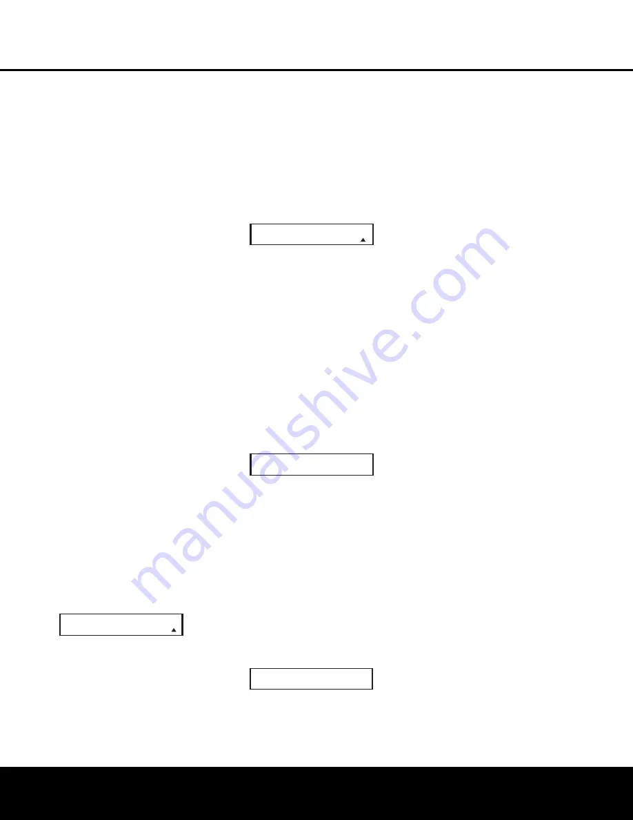
5. At the next menu screen on the remote, press the

Navigation Button

o

so that the bottom line

of the LCD display reads 

AUTO

(Figure 31) and

then press the 

Set Button

q

to enter the

Automatic programming mode.

Figure 31

6. As instructed on the next menu screen, press 

the 

Navigation Button

o

to begin the

automatic code search process. Your confirmation 
that the remote is sending out commands is the
movement of a square block across the top line
of the LCD display screen while the bottom line
reads 

PLEASE WAIT…

. You will also see the

transmit icon in the upper right corner of the LCD

display’s top line to remind you that the remote is
working even though you may not see anything
happening to the device being programmed.

7. It will take a few seconds for the remote to send

out the first group of commands, after which you
will see a new display in the LCD screen, as
shown in Figure 32. Following the instructions, if
the device being programmed has 

not

turned off,

press the 

Navigation Button

o

again to

send another group of codes. If the device being
programmed 

has

turned off, skip to Step 9.

Figure 32

8. By pressing the 

Navigation Button

o

again, the remote will send out a new set of 
commands. When it pauses, follow the instructions
shown in Step 7. Depending on how many codes
are stored for a specific device type, you may
have to repeat this process as many as 15 times.
Remember, if the device turns off, skip to Step 9.
When all the codes for the device being pro-
grammed have been tried, the instruction shown
in Figure 33 will appear. This means that the
codes for the product you are trying to program
are not in the AVR remote library and you will
have to “learn” them into the remote following the
instructions shown in the next section. Press the

Set Button

q

as instructed to exit the 

programming process.

Figure 33

9. If the device being programmed 

does

turn off 

after following the instructions in Step 7, you 
will need to verify the code set by pressing the

Numeric Keys

k

in sequence, as instructed in

Figure 32. Point the remote at the device being
programmed, and press the 

“1” Button

k

to

see whether the device turns back on.

10. After pressing and releasing the 

“1” Button

k

,

check to see whether the device has turned back
on. If it has, skip to Step 12. If it does not turn off,
press the 

“2” Button

k

, or the next button in

the numeric sequence if you are repeating the 
procedure, as instructed by the LCD screen in
Figure 34.

Figure 34

11. When pressing the “1” button does not turn 

the device being programmed back on, repeat 
the procedure by trying the remainder of the

Numeric Keys

k

in sequence, each time

pressing and then releasing the button to see
whether the new device turns back on. When it
does, skip to the next step. However, if you try all
10 numeric keys and find that the unit will not turn
on, you won’t be able to use this method to pro-
gram the device. Press the 

Clear Button

j

to

exit the programming process. You’ll need to follow
the Learning Commands instructions below to enter
the codes for this device into the AVR remote.

12. When pressing one of the numeric keys in Step

10 or 11 causes the device being programmed
to turn back on, follow the instructions shown in
Figure 32 and press the 

Set Button

q

within

five seconds of the device turning on. After you
press the Set button, the top line of the LCD dis-
play will read 

SAVING…

and then the word

SAVED

will flash four times in the center of the

bottom line.

13. When the codes are saved, the remote will return

to normal operation, and whenever you press 
the 

Input Selector Button

d

that was just 

programmed, the codes for the new device will 
be used. If no further buttons are pressed, the
remote will revert back to the default setting for
AVR commands.

Learning Commands

On occasions when the AVR remote does not contain
the codes for a particular product’s remote in its built-
in library, or when you wish to program a missing or
special function into one button of a device, the AVR
remote’s learning capability allows you to do that. To
teach commands from one product’s remote into the
AVR remote:

The AVR 435’s remote not only allows you to “learn”
in the commands from any compatible remote; it also
allows you to learn a separate code into the 

Input

Selector Buttons

d

. This unique capability allows

you to configure the remote so that whenever one of
these buttons is pressed, the remote will not only
select the codes for that device for itself, but it will
transmit a separately programmed remote code. This
is particularly valuable when your system includes a
source such as a cable box, satellite receiver or DVD
player with an HDMI or DVI output that is connected
directly to your video display. By programming the 

display’s

input selection remote code for the specific

device, you can, for example, press the VID 3/Cable

Input Selector Button

d

and not only have the

AVR switch to a cable set-top for audio selection and
have the AVR remote use remote codes for the cable
box, but you can send a code to the display that
selects the HDMI or DVI input used for a direct con-
nection between the set-top and your display.

Before learning codes, note that all buttons on the
remote may have a command “learned” except for

P O W E R   O N ?

Y

-

>

S E T   N -

>

1

~

0

R E A C H   E N D   P O I N T
E X I T   -

>

  S E T   K E Y

P O W E R   O F F ?

Y

-

>

  1

~

0   N -

>

P R O G R A M   D E V I C E
A U T O

44  CONFIGURING THE REMOTE

CONFIGURING THE REMOTE

AVR 435 OM   12/27/04  2:57 PM  Page 44


Содержание AVR 435

Страница 1: ...AVR435 AVR 435 AUDIO VIDEO RECEIVER OWNER S MANUAL Power for the Digital Revolution ...

Страница 2: ...ABLE OF CONTENTS Typographical Conventions In order to help you use this manual with the remote control front panel controls and rear panel connections certain conventions have been used EXAMPLE bold type indicates a specific remote control or front panel button or rear panel connection jack EXAMPLE OCR type indicates a message that is visible on screen or on the front panel information display EX...

Страница 3: ...o connections and system integration is a snap with the AVR 435 thanks to three assignable wide bandwidth inputs that are renameable To further enhance the viewing experience with digital sources or displays the AVR 435 s A V Sync Delay feature allows you to compensate for the loss of lip sync due to digi tal video delays individually for each input Full carrier IR outputs a bi directional RS 232 ...

Страница 4: ...weight of the AVR 435 and the heat generated by the amplifiers there is the remote possibility that the rubber padding on the bottom of the unit s feet may leave marks on certain wood or veneer materials Use caution when placing the unit on soft woods or other materials that may be damaged by heat or heavy objects Cleaning When the unit gets dirty wipe it with a clean soft dry cloth If necessary w...

Страница 5: ...will turn blue when the unit is on 2 Surround Mode Group Selector Press this but ton to select the top level group of surround modes Each press of the button will select one of the sur round mode categories Once the button is pressed so that the name of the desired surround mode category appears in the on screen display and in the Lower Display Line press the Surround Mode Selector 3 to cycle thro...

Страница 6: ...controls behind this door may be accessed gently pull the door down and towards you using either upper corner of the door Volume Control Turn this knob clockwise to increase the volume counterclockwise to decrease the volume If the AVR 435 is muted adjusting the volume control will automatically release the unit from the silenced condition Input Indicators One of these indicators will light to ide...

Страница 7: ...e and in the on screen display and then press either of the Buttons H to enter the desired boost or cut setting See page 32 for more information on the tone controls D Speaker Selector Button Press this button to begin the process of configuring the AVR 435 for the type of speakers it is being used with For complete information on configuring the speaker settings see page 26 E Channel Adjust Selec...

Страница 8: ... 34 33 32 31 37 36 35 34 33 32 48 49 50 51 47 46 45 44 43 42 33 34 35 36 37 38 39 40 41 48 49 46 47 44 45 42 43 38 39 40 41 31 32 30 28 29 25 26 27 28 29 30 24 23 22 21 20 31 37 36 35 34 33 32 31 37 36 35 34 33 32 48 49 50 51 47 46 45 44 43 42 33 34 35 36 37 38 39 40 41 48 49 46 47 44 45 42 43 38 39 40 41 31 32 30 28 29 25 26 27 28 29 30 24 23 22 21 20 31 37 36 35 34 33 32 31 37 36 35 34 33 32 48 ...

Страница 9: ...ound system use the brown and black ter minals are the surround back left channel positive and negative connections and the tan and black terminals are the surround back right positive and negative terminals For multiroom use connect the brown and black SBL terminals to the red and black connections on the left remote zone speaker and con nect the tan and black SBR terminals to the red and black t...

Страница 10: ...puts Connect the left right REC IN audio input jacks on a VCR or other video source to these jacks Video 2 Audio Inputs Connect the left right PLAY OUT audio output jacks on a VCR or other video source to these jacks Video 2 Audio Outputs Connect the left right REC IN audio input jacks on a VCR or other video source to these jacks 8 Channel Direct Inputs These jacks are used for connection to sour...

Страница 11: ...Y Channel Up Down Selector Z Transport Play Buttons a Delay Select Button b Speaker Select Button c Memory Button d Stereo Mode Select Button e DTS Neo 6 Mode Select Button f DTS Digital Mode Select Button g Dolby Mode Select Button h 6 8 Channel Input Select i Mute Button j Lens 1 2 3 4 5 6 7 9 i j A D F H J L N O P Q R S T U M V X 0 C K W Y Z a b d 8 G B e f h c E I g AVR 435 MUTE VDI TUNING NOT...

Страница 12: ...sed to enter letters and num bers when renaming devices in the LCD Information Display See page 50 for more information on renam ing devices and keys B Tuning Mode Button Press this button to change the tuner mode between manual and automatic When the button is pressed so that AUTO STEREO appears in the Upper Display Line and in the on screen display only stations with acceptable signal quality wi...

Страница 13: ...s button controls the tone mode settings enabling adjustment of the bass and treble boost cut You may also use it to take the tone controls out of the signal path completely for flat response The first press of the button displays a TONE IN message in the Lower Display Line and in the on screen display To take the controls out of the signal path press either of the Navigation Buttons o until the d...

Страница 14: ...on stereo playback modes e DTS Neo 6 Mode Select Button Press this button to select a DTS Neo 6 mode See page 34 for the available DTS Neo 6 options f DTS Digital Mode Select Button When a DTS encoded digital source is playing each press of this button will scroll through the available DTS modes The specific choice of modes will vary according to the type of encoding on the disc and your system s ...

Страница 15: ...sor that is connected to the Multiroom IR Input Jack f this button will raise or lower the volume in the remote room Play Forward Reverse Stop Buttons Press these buttons to control compatible Harman Kardon CD DVD or cassette players Mute Button When the Zone II remote is used in the room where the AVR 435 is located press this button to temporarily silence the unit When it is used in a remote roo...

Страница 16: ...amplifier When a passive subwoofer is used the connection first goes to a power ampli fier which will be connected to one or more sub woofer speakers If you are using a powered sub woofer that does not have line level input connec tions follow the instructions furnished with the speaker for connection information 9 If an external multichannel audio source with 5 1 outputs such as an external digit...

Страница 17: ...te zone from the one selected for use in the main room Depending on your system s requirement three options are available for audio connection Option 1 Use high quality shielded audio intercon nect cable from the AVR 435 s location to the remote room In the remote room connect the interconnect cable to a stereo power amplifier The amplifier will be connected to the room s speakers At the AVR 435 p...

Страница 18: ...uipped with two accessory AC outlets They may be used to power accessory devices but they should not be used with high current draw equip ment such as power amplifiers The total power draw to each outlet may not exceed 100 watts The Switched AC Accessory Outlet is powered only when the unit is on This is recommended for devices that have a mechanical power switch that may be left in the ON positio...

Страница 19: ...ion for 5 1 systems It is required for 7 1 operation speakers should be located so that the bottom of the cabinet is at least 2 feet higher than the listeners ears when the listeners are seated in the desired area Rear surround speakers are required when a full 7 1 channel system is installed and they may also be used in 5 1 channel systems as an alternative mount ing position when it is not pract...

Страница 20: ... OSD system is in use the menu selec tions are not shown in the Upper or Lower Display Lines When the full OSD menu system is used OSD ON will appear in the Upper Display Line to remind you that a video display must be used When the semi OSD system is used in conjunc tion with the discrete configuration buttons the on screen display will show a single line of text with the current menu selection T...

Страница 21: ...been selected press the Navigation Button o to go to the next setting If you wish to associate one of the digital inputs with the selected input source or change the default digital input selection press the Navigation Button o on the remote while the IN OUT SETUP menu Figure 2 is on the screen and the on screen cursor will drop down to the DIGITAL IN line Press the Navigation Button o until the n...

Страница 22: ...vigation Button o to scroll through the avail able choices and then press the Navigation Button o so that the cursor is next to BACK TO MASTER MENU to continue the setup process The following few paragraphs detail the instructions needed for modes with multiple choices On the DOLBY SURROUND menu Fig 5 choices include Dolby Digital Dolby Pro Logic II Dolby Pro Logic IIx Movie and Music Dolby Pro Lo...

Страница 23: ...with the Navigation Button o on the remote select from one of the DSP surround modes that are designed for use with two channel stereo programs to create a variety of sound field pre sentations The choices available are Hall 1 Hall 2 or Theater The Hall and Theater modes are available in both five and six channel verisions depending on your system configuration See page 34 for a com plete explanat...

Страница 24: ...earing protection before mov ing to the next step If you do not wish to start the test process at this time press the Navigation Button o to return to either the EzSet EQ menu or the Master Menu and press the Set Button q To begin the EzSet EQ Near Field measurements press the Navigation Button o so that ON is highlighted in reverse video and press the Set Button q NOTE Once the EzSet EQ process s...

Страница 25: ...hat it is close to and pointing towards the front left speaker and with the on screen Ô cursor pointing to 1 FL SPEAKER and press the Set Button q Figure 13 Step 9 You will now see a Warning message similar to the one shown in Figure 7 except that it will contain an option to return to the NEAR FIELD EQ SELECT menu Figure 13 as well as the ability to return to the MASTER MENU If you are ready to p...

Страница 26: ...r Crossover Delay Adjust and Channel Adjust includes a line that reads EZSET SETTINGS When the default setting of OFF is shown you are able to make any required adjustments that are available on that menu However you may change the setting to ON at any time to recall the settings established when EzSet EQ was last run It is also important to note that when the EzSet EQ settings are in use the AVR ...

Страница 27: ...the center channel output The receiver will operate in a phantom center channel mode and center channel information will be sent to the left and right front chan nel outputs When only front left and right speakers are used with no center or surround speakers Dolby Virtual Speaker is a good alternative mode When you have completed your selection for the cen ter channel press the Navigation Button o...

Страница 28: ...justed as the feed will be full range with no sound being derived for the subwoofer at that position To make changes to the speaker crossovers or LFE high pass filter setting go to the SPKR X OVER submenu within the MANUAL SETUP menu Fig 16 To do this first press the OSD Button U so that the MASTER MENU Figure 1 appears Next press the Navigation Button o until the cursor is on the MANUAL SETUP lin...

Страница 29: ... individ ual settings so that the picture and sound are brought back together We recommend that this adjustment be made using the direct access controls on the remote as shown below That enables you to see the image while making the adjustment however you may also adjust it here using the menu system To adjust the A V Sync delay press the Navigation Button o so that the Ô cursor is pointing to the...

Страница 30: ...m each speaker Adjustments should be made with the Navigation Button o on the remote only NOT the main volume controls If you are using a sound pressure level SPL meter for precise level adjustment set the volume so that the meter reads 75dB C Weighting Slow When all channels have an equal volume level the adjustment is complete To exit this menu press the Navigation Button o until the cursor is n...

Страница 31: ...y make any other adjustments to the system parameters If the changes just made com plete the manual adjustments needed press the OSD Button U to exit the menu system and resume normal system operation Additional Input Adjustments After one input has been adjusted for Surround mode digital input if any speaker type and output levels go back to the INPUT SETUP line on the MASTER MENU Figure 1 and en...

Страница 32: ... in the Upper Display Line and in the front panel Input Indicators When an audio only source is selected the last video input used remains routed to the Video 1 Video 2 Video Outputs and Video Monitor Outputs This permits simultaneous viewing and listening to different sources When a composite or S video source is selected the video signal for that input will be routed to the Video Monitor Output ...

Страница 33: ...y them straight through to the volume control without any further digital processing To listen to a program in traditional two channel stereo using the front left and front right speakers only plus the subwoofer if installed and configured press the Stereo Mode Select Button until SURROUND OFF appears in the Lower Display Line From the front panel press the Surround Mode Group Selector 2 until the...

Страница 34: ...ource that contains Dolby Surround or similar matrix encoding Logic 7 C delivers for increased center channel intelligibility and more accurate placement of sounds with fades and pans The Logic 7 M or music mode enhances the listening experience by presenting a wider front soundstage and greater rear ambience Both Logic 7 modes also direct low frequency information to the subwoofer if installed an...

Страница 35: ...utomati cally be selected For example DTS bitstreams will cause the unit to switch to DTS decoding and Dolby Digital bitstreams will enable Dolby Digital decoding When the unit senses PCM data from CDs or LDs you may select any of the standard Dolby or DTS surround modes or Logic 7 Since the range of available sur round modes is dependent on the type of digital data that is present the AVR 435 sho...

Страница 36: ...The AVR 435 will automatically sense changes to the bitstream and channel count and reflect them in these indicators The letters used by the Speaker Channel Input Indicators will flash to indicate when a bitstream has been interrupted This will happen when a digital input source is selected before the playback starts or when a digital source such as a DVD is paused The flashing indicators remind y...

Страница 37: ...ess the Tuning buttons again to scan to the next receivable station When the button is pressed so that MANUAL MONO appears in the Upper Display Line each tap of the Selector will increase or decrease the frequency by one increment When the tuner receives a strong enough signal for adequate reception MANUAL TUNED will appear in the Lower Display Line 4 Stations may also be tuned directly in either ...

Страница 38: ...e for 5 seconds the AVR 435 will return to normal operation The output levels may also be adjusted using the on screen menu system to either the internal test tone or an external test disc by following the instructions shown on page 29 Dim Function Since the AVR 435 will often be used when movies or other video programming is viewed under low light conditions you may wish to lower the brightness o...

Страница 39: ...f If you wish to make other adjustments press the Navigation Button o until the Ô cursor is next to the desired setting or the BACK TO MASTER MENU line and press the Set Button q If you have no other adjustments to make press the OSD Button U to exit the menu system Turn On Volume Level As is the case with most audio video receivers when the AVR 435 is turned on it will always return to the volume...

Страница 40: ...he AVR 435 includes both analog and digital audio inputs for all sources In most cases you will want to use one or the other but not both However in some circumstances it is desirable to make both an analog and digital con nection between a source device and the AVR An important application for dual audio connections is with cable or satellite boxes where the audio output may change depending on t...

Страница 41: ... multi room operation Press the OSD Button U to bring the MASTER MENU Figure 1 to the screen Press the Navigation Button o until the on screen Ô cursor is next to the MULTI ROOM line Press the Set Button q to enter the MULTI ROOM menu Figure 23 Figure 23 When the MULTI ROOM menu appears the cursor will be at the MULTI ROOM line Since this line is used to turn the system on and off don t make an ad...

Страница 42: ...room that is connected to the AVR it is also possible to change those settings from the main listening room This is useful for situations where some or all of the remote rooms do not have an IR sensor or to take control over the remote room without actu ally being in that room In addition to using the MULTIROOM menu as shown on the previous page you may change the source or volume in the remote zo...

Страница 43: ...ning the commands from the product s original remote into the AVR remote The instructions for Learning Commands are on page 44 7 The next step is important as it determines which codes will operate the source device or display Point the AVR remote at the device being pro grammed and following the instructions shown in the remote s LCD Information Display c press and release the Numeric Keys k show...

Страница 44: ... as instructed to exit the programming process Figure 33 9 If the device being programmed does turn off after following the instructions in Step 7 you will need to verify the code set by pressing the Numeric Keys k in sequence as instructed in Figure 32 Point the remote at the device being programmed and press the 1 Button k to see whether the device turns back on 10 After pressing and releasing t...

Страница 45: ...dows on the two remotes are facing one another 9 Continue to hold the button on the original remote until the LCD display changes again If the code was successfully learned you will see the display shown in Figure 39 In that case go to Step 10 If the LEARN FAILED display Figure 40 appears again you may either try to program the key again or press the Navigation Button o to stop the process It is p...

Страница 46: ...D 2 TV Button transmit the commands used to control a VCR Press the Set Button q when the desired device combination appears Figure 46 5 Once the new device is selected the remainder of the process will select the codes for the specific brand to be used and for that reason they are identical to the way a device is programmed using manual entry Continue the process as outlined in the next few steps...

Страница 47: ...een press the first key you wish to be transmitted in the macro In our example we first want the AVR 435 to turn on so the Power Button 1 should be pressed Figure 52 8 Once the first command button for the macro has been pressed continue to press the buttons you wish to be part of the macro in the order they will be used Press each button within five seconds of the last button remembering to press...

Страница 48: ... device Punch through enables you to easily program the remote to do this Volume Punch Through Follow these steps to enable the Volume Up Down and Mute controls from one device to be used when the remote is otherwise programmed for a different device NOTE FOR VOLUME PUNCH THROUGH The remote s default settings are for the AVR 435 s vol ume controls to be used when any input or device is selected wi...

Страница 49: ...d when those buttons Y are pressed while the master device is in use Returning the Channel Control Settings to Default Operation If you wish to remove the Channel Punch Through so that the commands for Channel Up Down are returned to the factory default setting follow the steps shown above except that in Steps 4 and 5 select the same device for both the DEVICE IN USE on the left side of the bottom...

Страница 50: ... key For example since the first letter we need to rename the input to HDTV Tuner is an H you would locate the H above the 4 button and press the button twice The first press shows a G the second press changes it to an H Consult the table at the end of this section to see which characters pressing a partic ular button generates 7 After you enter the first letter of the new device name there are th...

Страница 51: ...acter a To enter a letter that requires a different numeric key to be pressed simply press that button The cursor will automatically move to the next position and the first letter accessed by the new button will appear Following our example the next letter needed is an O so you would press the 6 button once b To enter a letter that uses the same numeric key you must first press the Navigation Butt...

Страница 52: ...ave to press the AVR Selector e in order to use the remote to operate the AVR for functions such as surround mode selection but the Volume and Mute controls will continue to remain active in their AVR modes at all times 4 Press the Set Button q one more time The LCD display will show the word SAVING on the top line for about 2 seconds and then flash SAVED four times on the bottom line to indicate ...

Страница 53: ...nctions of the remote may consume significantly more battery power than normal remote operation While the batteries should last for four to six months in normal operation you may find that they need to be changed sooner after the remote is programmed for the first time When the batteries approach a level below which the remote will not function the remote s LCD screen will display a LOW BATTERY wa...

Страница 54: ...to operate Additional cooling may not be required The fan is activated only when additional cooling is required due to high internal temperature It is normal for the fan to be inactive at normal volume levels In addition to the items shown above additional information on troubleshooting possible problems with your AVR 435 or installation related issues may be found in the list of Frequently Asked ...

Страница 55: ...0Hz 50MHz 3dB General Power Requirement AC 120V 60Hz Power Consumption 59W at Power On idle 1 000W at rated power output 7 channels driven Dimensions Product Shipping Width 17 3 inches 440mm 20 1 inches 510mm Height 6 5 inches 165mm 10 inches 254mm Depth 17 1 inches 435mm 22 2 inches 565mm Weight 39 lb 18 6kg 45 lb 21 4kg Depth measurement includes knobs buttons and terminal connections Height mea...

Страница 56: ...7 20 21 35 Output Level Adjustments 29 31 Output Level Trim Adjustment 38 PCM 36 Power Switches 5 7 12 15 20 32 Preset Stations 6 13 37 Processor Reset 54 RS 232 Port 17 18 Rear Panel Connections 8 10 Recalling Preset Stations 6 13 37 Recording 37 38 Remote Control Backlight 52 Batteries 20 Changing Devices 46 Channel Punch Through 49 Device Priority 52 Functions 11 15 Learning Codes 44 46 Macros ...

Страница 57: ...NOTES NOTES 57 NOTES 57 ...

Страница 58: ...NOTES 58 NOTES ...

Страница 59: ...NOTES NOTES NOTES 59 ...

Страница 60: ... 250 Crossways Park Drive Woodbury New York 11797 www harmankardon com 2005 Harman International Industries Incorporated Part No ZKD1101HA00 3 ...

Отзывы: