Any-Weigh™ Series Floor Scales
25
Step 15.
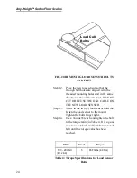
Run the load sensor cable through the
channel to the summing box. Bundle up
any excess cable and store it in the chan-
nel. DO NOT CUT THE CABLE TO
MAKE IT FIT BETTER. If you cut the
cable, you will not get correct readings
from the load sensors.
Step 16.
Reconnect the cable wires according to the
color code in Step 3 to the correct load
sensor connector.
OPTIONAL PIT
FRAMES
About Pit Frames
The pit frame optional accessory is a one-piece
welded unit with no additional welding required.
There are 3 different type frames with many sizes for
each type. This accessory is designed for in-floor or
'flush' applications. In general, a hole is cut in the con-
crete, the pit-frame accessory is installed in the hole,
then concrete is poured around and under the frame.
Once cured, the scale platform is set into the frame
and installation can be completed.
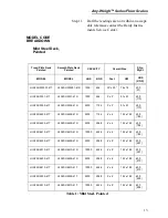
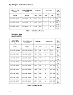
Standard duty frames are available in mild steel or
stainless steel for all the floor scale sizes. The con-
crete work and frame setting is usually done by a con-
tractor, with a scale technician completing the project
by setting and installing the scale.
•
A soil bearing pressure of at least 1,000 lbs
per square foot is required. The corner pier
should be designed to support at least two
thirds of the total capacity of the scale.
•
A 3/4” diameter conduit for the scale inter-
face cable is recommended. The pit frame is
arranged with a 1 1/8” diameter hole for a
cable exit. Locate the conduit to match the
hole location.
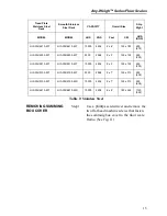
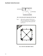
Step 1.
Place the pit frame in the approximate
position it will occupy on the floor. (See
Fig. 21)
Содержание Any-Weigh
Страница 4: ......
Страница 8: ...Any Weigh Series Floor Scales II ...
Страница 52: ...Any Weigh Series Floor Scales ...

