background image

Any-Weigh™ Series Floor Scales

4

crate bottom. See Tables 2 & 3 for ship-
ping weights.

 Step 5.

Be sure to use all safety precautions when 
lifting the platform so that it does not fall 
on equipment or personnel. It is highly 
recommended that blocks be placed under 
the platform before working near the plat-
form scale.

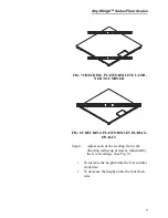
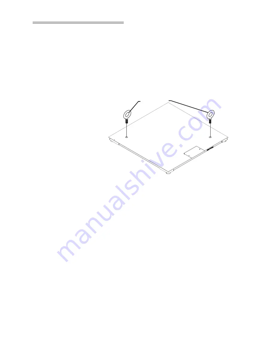
 FIG. 1 INSTALLING THE CLOSED EYE-

BOLTS INTO THE TOP PLATE

COMPONENT 
DESCRIPTIONS

1.

Steel Plate Platform - The platform material is 
either low carbon steel plate or 304 stainless steel 
plate. The low carbon steel platform cover is 
made from a single piece of 1/4" A36 carbon 
steel floor plate (skid resistant) or smooth steel 
plate.   The steel platforms are primed and coated 
with a tough weather resistant paint (See Paint 
Specifications). The 304 stainless steel platform 
is made from a single piece of 1/4" diamond tread 
(Conforms to ASTM A793-85) floor plate (skid 
resistant) or smooth stainless steel plate with a 
bead blast finish.

2.

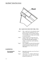
Summing Junction Card Assembly - Accessed 
by unfastening the face plate on the center side of 
the platform. (See Fig.2) The summing junction 
card routes the excitation voltage to each of the 
four load sensors and sums the weight signal 

Closed Eye Bolts
for Lifting the 
Platform Scale

Содержание Any-Weigh

Страница 1: ...k Drive Suite 150 San Diego CA 92121 San Diego CA 92123 1825 Phone 858 278 2900 FAX 858 278 6700 Web Site http www hardyinst com Hardy Instruments Document Number 0596 0280 01 Rev D Copyright October 2003 Hardy Instruments Inc All Rights Reserved Printed in the U S A 941028 ...

Страница 2: ...pplications We re ready to support you with Installation and start up Routine maintenance and certification Plant audits and performance measurement Emergency troubleshooting and repair To request Emergency Service and Troubleshooting Start up Installation Calibration Verification or to discuss a Maintenance Agreement please call 800 821 5831 Ext 1757 or Emergency Service after hours Standard Hour...

Страница 3: ...NSTRU MENTS IMMEDIATELY BY CALLING FAXING OR E MAILING TO Hardy Service Center HARDY INSTRUMENTS INC 9440 Carroll Park Drive Suite 150 San Diego CA 92121 Phone 800 821 5831 858 278 2900 FAX 858 278 6700 E mail disupport hardyinst com Web Address www hardyinst com TO RETURN DEFECTIVE OR DAMAGED PRODUCT S CALL HARDY TECHNICAL SUPPORT FOR A HARDY SERVICE TICKET NUMBER HST YOUR COMPANY NAME ADDRESS TE...

Страница 4: ......

Страница 5: ...nge 1 Temperature Effect 1 Cable Length 1 Materials of Construction 1 Steel 1 Paint 2 Foot Elastomer 2 Grade Level 2 Accessories 2 Anchor Bolt Holds 2 Approvals 2 NEMA Rating 2 Test Criteria 2 GENERAL INFORMATION 2 UNPACKING 3 COMPONENT DESCRIPTIONS 4 SITE PREPARATION 5 Precautions 6 FLOOR SCALE INSTALLATION 7 CALIBRATION 10 Pre Calibration Procedures 10 C2 Second Generation Calibration 11 Test We...

Страница 6: ...teel Deck 304 SS 14 REMOVING SUMMING BOX COVER 15 Installing the Leveling Feet 18 INSTALLING A LOAD SENSOR 21 OPTIONAL PIT FRAMES 25 About Pit Frames 25 OPTIONAL ACCESS RAMPS 29 Access Ramp Installation 29 OPTIONAL BOLT DOWN PLATES 31 Bolt Down Plates Installation 32 OPTIONAL BUMPER GUARDS 33 TROUBLESHOOTING 36 INSTRUMENTATION INTERFACE CABLE COLOR CODES 37 ...

Страница 7: ...11 REMOVING THE SUMMING BOX COVER 16 FIG 12 REMOVING THE SUMMING BOX LID 17 FIG 13 REMOVING THE SUMMING BOX LID 18 FIG 14 INSERTING THE LEVELING FOOT INTO THE LOAD SENSOR 19 FIG 15 INSIDE VIEW 20 FIG 16 OUTSIDE VIEW 20 FIG 17 ALL FOUR FEET INSTALLED 21 FIG 18 SUMMING CARD 21 FIG 19 CORD GRIP 23 FIG 20 REMOVING LOAD SENSOR BOLTS AND FEET 24 FIG 21 FOUNDATION FOR THE PIT FRAME 26 FIG 22 PIT FRAME DI...

Страница 8: ...Any Weigh Series Floor Scales II ...

Страница 9: ...EXCI TATION VOLTAGE ABOVE 5 VDC Total Error 0 03 of FS Output Maximum Overload 150 of the Rated Scale Capacity Endloading 100 of the Rated Scale Capacity Temperature Range Safe 40º to 80º Degrees C 40º to 176º F Compensated 10 to 40 Degrees C 14º to 104º Degrees F Temperature Effect On Output 0 0011 of load Deg C On Zero 0 0011 of FSO Deg C Cable Length 20 feet C2 Cable NOTE To purchase C2 Cable c...

Страница 10: ...p Approvals NTEP Class III Number 04 087 NEMA Rating Summing Junction Box Enclosure NEMA 4X Stain less Steel Test Criteria Must exclude at least 65 GPM of wate from 1 inch nozzle deliverd from a distance not less than 10 ft for 5 minutes GENERAL INFORMATION The Hardy Instruments AnyWeigh Series Floor Scales are designed for applications that require a low profile weighing surface with high commerc...

Страница 11: ...ed Inspect the container for any signs of damage that might occur during shipment Since almost all of the Floor Scales are shipped F O B factory such damage is normally the responsi bility of the carrier and should be reported to them Step 1 Remove the banding straps and any ship ping restraints WARNING DO NOT USE HOOKS OR UNCLOSED EYE BOLTS OR ATTEMPT TO LIFT THE SCALE MANUALLY FAILURE TO USE THE...

Страница 12: ... carbon steel platform cover is made from a single piece of 1 4 A36 carbon steel floor plate skid resistant or smooth steel plate The steel platforms are primed and coated with a tough weather resistant paint See Paint Specifications The 304 stainless steel platform is made from a single piece of 1 4 diamond tread Conforms to ASTM A793 85 floor plate skid resistant or smooth stainless steel plate ...

Страница 13: ...installed A built in sys tem diagnostics utility continuously monitors the weighing system for possible malfunctions This capability also allows the operator to rapidly troubleshoot a weighing system from the control ler or indicator 5 Leveling Feet Each AnyWeigh series scale comes with four 4 304 stainless steel adjustable leveling feet The leveling feet are adjustable to a maximum of 7mm 275 The...

Страница 14: ...tore other equipment on the scale even temporarily when it is not used or in storage Do not allow debris to accumulate on around or under the scale Do not set the scale in water or allow water to accumulate around the scale Always pro vide proper drainage Do not let moisture get on or into any of the electrical interconnections Do not allow static or other electrical dis charges go through the sca...

Страница 15: ...e operating location Make sure that the platform height is within 3 to 3 275 as measured from the top of the cover plate to the top of the floor surface See Fig 4 NOTE With the scale in place the clearance around the edge of the platform and pit coping should be 1 4 to 3 8 FIG 4 MAXIMUM HEIGHT Load and unload heavy equipment in this direction only 3 275 83 1mm ...

Страница 16: ... sure that the platform mounting sur face is level to 1 8 Step 3 Use a spirit level to check if the platform is level side to side corner to corner and diagonally See Figs 9 10 11 12 FIG 5 SPIRIT LEVEL FIG 6 CHECKING PLATFORM LEVEL SIDE TO SIDE ...

Страница 17: ... CORNER FIG 8 CHECKING PLATFORM LEVEL DIAG ONALLY Step 4 Adjust each of the leveling feet in the direction either up or down indicated by the level readings See Fig 9 To increase the height rotate the foot counter clockwise To decrease the height rotate the foot clock wise ...

Страница 18: ...op of the platform to the floor surface at each cor ner All the measurements should be within 3º of each other and the platform should be level Step 7 If the installation requires bolt down plates to keep the floor scale in place go to the Optional Bolt Down Plates Section for instructions CALIBRATION Pre Calibration Procedures Step 1 Open the Junction box cover See Fig 11 for Instructions Step 2 ...

Страница 19: ...ition C2 electronically calibrates a scale sys tem without the need for test weights This feature is in all Hardy weight or rate controllers and in the Allen Bradley weight modules Step 1 Refer to the Hardy weight or rate control ler manuals or the Allen Bradley module manual for instructions Test Weight Calibration Hard Cal Requirements Test weight calibration requires the use of certified class ...

Страница 20: ...N Step 1 Get a test weight that is equal to 10 of the full scale capacity Step 2 Place the test weight at Position 1 on the platform See Fig 10 FIG 10 SCALE VERIFICATION POSITION 3 Step 3 Write down the weight for position 1 Step 4 Place the weight at position 2 Step 5 Write down the weight for position 2 Step 6 Place the weight at position 3 Step 7 Write down the weight for position 3 Step 8 Plac...

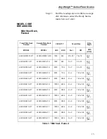
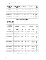
Страница 21: ...U3302 41S 2500 1134 3 x 3 91 x 91 250 113 HI AFSU4402 41T HI AFSU4402 41S 2500 1134 4 x 4 122 x 122 405 184 HI AFSU4405 41T HI AFSU4405 41S 5000 2268 4 x 4 122 x 122 405 184 HI AFSU4410 41T HI AFSU4410 41S 10000 4536 4 x 4 122 x 122 405 184 HI AFSU4505 41T HI AFSU4505 41S 5000 2268 4 x 5 122 x 152 500 227 HI AFSU4510 41T HI AFSU4510 41S 10000 4536 4 x 5 122 x 152 500 227 HI AFSU4605 41T HI AFSU460...

Страница 22: ...Y Overall Size Ship Wght MODEL MODEL LBS KGS Feet CM LBS KGS HI AFSU303001 43T HI AFSU303001 43S 1000 454 30 x 30 76 x 76 200 91 HI AFSU3301 43T HI AFSU3301 43S 1000 454 3 x 3 91 x 91 250 113 HI AFSU3302 43T HI AFSU3302 43S 2500 1134 3 x 3 91 x 91 250 113 HI AFSU4402 43T HI AFSU4402 43S 2500 1134 4 x 4 122 x 122 405 184 HI AFSU4405 43T HI AFSU4405 43S 5000 2268 4 x 4 122 x 122 405 184 HI AFSU4410 ...

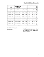
Страница 23: ...SU5505 43T HI AFSU5505 43T 5000 2268 5 x 5 152 x 152 650 295 HI AFSU5510 43T HI AFSU5510 43T 10000 4536 5 x 5 152 x 152 650 295 HI AFSU5705 43T HI AFSU5705 43T 5000 2268 5 x 7 152 x 213 900 408 HI AFSU5705 43T HI AFSU5705 43S 10000 4536 5 x 7 152 x 213 900 408 HI AFSU6810 43T HI AFSU6810 43S 10000 4536 6 x 8 183 x 244 1150 522 Tread Plate Stainless Steel Deck Smooth Stainless Steel Deck CAPACITY O...

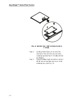
Страница 24: ...G BOX COVER Step 2 Gently pull the frame cover out of the enclosure You now have access to the summing junction box C2 Certified Cable as shipped Step 3 Using a phillips head screwdriver remove all the screws that fasten the cover to the summing box See Fig 12 ...

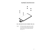
Страница 25: ...Weigh Series Floor Scales 17 FIG 12 REMOVING THE SUMMING BOX LID Step 4 Take the lid off the junction box so that you can see all the wiring from the load sensors and to the instrument indicator See Fig 13 ...

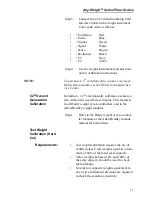
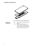
Страница 26: ...the Leveling Feet Step 1 Remove the lock bolt and nut from the lev eling foot Step 2 With the scale raised and securely blocked insert the leveling foot into the load sensor Make sure the through hole in the foot is aligned with the bottom through hole on the load sensor See Fig 14 ...

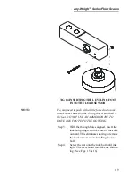
Страница 27: ...at is attached to the foot DO NOT USE A HAMMER OR TRY TO DRIVE THE FOOT INTO THE HOUSING Step 3 With the through holes aligned insert the lock bolt going from the center of the scale outward This eliminates having to remove the load sensors when installing the lock bolt Step 4 Screw the nut onto the lock bolt until it is tight The feet should look like the follow ing See Figs 15 16 ...

Страница 28: ...Any Weigh Series Floor Scales 20 FIG 15 INSIDE VIEW FIG 16 OUTSIDE VIEW Step 5 Install all four 4 feet See Fig 17 ...

Страница 29: ...ING A LOAD SENSOR Step 1 Shut all power off to the floor scale Step 2 To gain access to the Summing Card fol low the instructions above You do not have to remove the summing card or the bottom of the Junction box to install a new load sensor See Fig 18 FIG 18 SUMMING CARD ...

Страница 30: ... have been removed Color code wires are as follows Excitation Red Signal Green Signal White Excitation Black C2 Grey C2 Violet Step 4 Loosen the cord grip nut for the load sen sor cable you want to remove See Fig 19 Load Sensor Connector Load Sensor 1 TB1 Load Sensor 2 TB2 Load Sensor 3 TB3 Load Sensor 4 TB4 To Instrument TB5 Table 3 Summing Card Load Sensor Connectors ...

Страница 31: ... completely over and let the top plate rest on blocks for easier access to the feet Step 7 Block the floor scale adequately so that the platform will not drop on any machinery or personnel Step 8 Remove the lock bolt on the load sensor foot you are removing Store in a safe place so that you don t forget to install it Step 9 Pull the load sensor leveling foot out of the load sensor Step 10 Use a so...

Страница 32: ...HE OLD CABLE ON THE NEW LOAD SENSOR Step 13 Screw in the two 2 load sensor bolts that fasten the load sensor to the mount Tighten the bolts finger tight Step 14 Use a Torque Wrench and tighten the bolts to the torque rating in Table 4 It is a good idea to switch back and forth between each bolt until the torque value has been reached BOLT Grade Torque 500 20 UNC M12 8 8 5 65 Ft Lbs 90 Nm Table 4 T...

Страница 33: ...e the pit frame accessory is installed in the hole then concrete is poured around and under the frame Once cured the scale platform is set into the frame and installation can be completed Standard duty frames are available in mild steel or stainless steel for all the floor scale sizes The con crete work and frame setting is usually done by a con tractor with a scale technician completing the proje...

Страница 34: ...FIG 21 FOUNDATION FOR THE PIT FRAME Step 2 Mark out the position of the hole to be made The hole MUST be a minimum of 12 larger than the pit frame on all sides See Fig 22 FIG 22 PIT FRAME DIMENSIONS 11 279 4mm 3 4375 87 3mm 8 Typ 8 Typ ...

Страница 35: ...APF5510 3 5 x 5 152cm x 152cm Stainless Steel HI APF5710 3 5 x 7 152cm x 213cm Stainless Steel HI APF6810 3 6 x 8 183cm x 244cm Stainless Steel Table 5 Pit Frame Stainless Steel Model Numbers and Dimensions Model Number Platform Size Feet Platform Size CM Material HI APF3310 1 3 x 3 91cm x 91cm Mild Steel HI APF4410 1 4 x 4 122cm x 122cm Mild Steel HI APF4510 1 4 x 5 122cm x 152cm Mild Steel HI AP...

Страница 36: ...he hole across the opening See Fig 7 Step 7 Use soft wire and make 2 loops by twist ing wire around each 2 x 4 and the frame Step 8 With the frame supported by the wire and 2 x 4 s use a spirit level to set the frame flush with the surrounding floor level the frame to within 1 8 corner to corner side to side and diagonally and at the correct height by twisting or untwisting the wires See Fig 7 Ste...

Страница 37: ...through the con duit OPTIONAL ACCESS RAMPS Optional access ramps are available in low carbon steel or stainless steel The low carbon ramps are con structed of Skid Resistant tread A36 low carbon steel floor plate The Stainless Steel ramps are con structed of 304 Stainless Steel diamond tread floor plate All ramps are thirty inches 30 76 2 centime ters long in the direction of travel and provide a ...

Страница 38: ...H RETAINER PLATES Step 3 Drill the two 2 outer holes using a ham mer drill See Specifications Anchor Bolt Holds above for hole dimensions Step 4 Insert the anchor bolts with the nut and washer already ON See Fig 26 FIG 26 INSTALLING ANCHORS FOR RAMP ...

Страница 39: ...ten the nuts securely Step 10 Note the following If two ramps are installed NO other bolt down plates are needed If one ramp is installed then a set of two bolt down plates are needed Only two ramps total may be installed on opposite sides of a scale platform OPTIONAL BOLT DOWN PLATES Bolt down plates are used to keep the scale from slid ing or moving when loads are applied The plates are bolted v...

Страница 40: ...p 2 Place the bolt down plate under the foot plate edge should extend out from under the scale Step 3 Drill two 2 holes using a hammer drill See Specifications Anchor Bolt Holds above for hole dimensions Insert anchor bolts with the nut and washer already attached Step 4 Tap the anchor bolts into the hole then tighten the nuts securely Step 5 Repeat this process for each plate used in your install...

Страница 41: ...DS Bumper guards are designed to help protect the plat form from direct hits from forklift traffic The guards are slightly higher than the scale and will help deflect the forks Step 1 Place the bumper guard so it will protect the platform from non scale traffic and not touch or interfere with the platform s movement See Figs 28 29 FIG 28 BUMPER GUARD GAP REQUIRE MENT ...

Страница 42: ...nchor bolts with the nut and washer already installed Step 4 Tap the anchor bolts into the hole then tighten the nuts securely Bumper Guard Material Length Shipping Wght Use on Scale Model Model Ft cm lbs Kg HI ABG03 1 HI ABG03 3 Mild Steel Stainless Steel 3 91 100 45 36 HI AFSU3301 4XT HI AFSU3302 4XT HI AFSU3301 4XS HI AFSU3302 4XS Table 8 BUMPER GUARD MODEL NUMBERS AND COMPATIBILITY CHART ...

Страница 43: ...10 4XT HI AFSU5705 4XT HI AFSU5710 4XT HI AFSU4505 4XS HI AFSU4510 4XS HI AFSU5505 4XS HI AFSU5510 4XS HI AFSU5705 4XS HI AFSU5710 4XS HI ABG06 1 HI ABG06 3 Mild Steel Stainless Steel 6 183 135 61 24 HI AFSU4605 4XT HI AFSU4610 4XT HI AFSU6810 4XT HI AFSU4605 4XS HI AFSU4610 4XS HI AFSU6810 4XS HI ABG07 1 HI ABG07 3 Mild Steel Stainless Steel 7 213 190 86 18 HI AFSU5705 4XT HI AFSU5710 4XT HI AFSU...

Страница 44: ... Packing material or debris wedged or built up under neath the platform Cause 2 Platform scale is not wired correctly to the weigh instrument Cause 3 Weigh Process Controller Malfunction Remedies Carefully lift the platform high enough to safely remove the built up debris Check for loose connections or broken wires Check the wiring color code to be sure that the wires are routed correctly If they ...

Страница 45: ...in the summing junction card enclo sure Cause 2 High voltage wires close to the load sensor cable Remedy 2 Move the high voltage wires away from the load sen sor cable Cause 3 Instrument or floor scale improperly grounded i e one or both not to connected to earth ground Remedy 3 Make sure that the weigh instrument and the floor scale platform cover are both connected to earth ground Cause 4 High s...

Страница 46: ...Any Weigh Series Floor Scales 38 SIGNAL GREEN SIGNAL WHITE SENSE BROWN EXCITATION BLACK C2 GREY C2 VIOLET SHIELD ORANGE ...

Страница 47: ...duction Technology 1 3 Block the Floor Scale 1 23 Bolt Down Plates Installation 1 32 Bundle 1 25 C C2 Certified Summing Card Interface Cable 1 11 C2 Certified Cable 1 10 C2 Second Generation Calibration 1 11 C2 Second Generation Calibration system 1 3 Cable Length 1 1 Calibration 1 10 Chain 1 23 Closed Eye Bolts 1 23 Color Code Wires 1 22 Commercial Accuracy 1 2 Component Descriptions 1 4 Conduit ...

Страница 48: ...affic 1 33 G Grade Level 1 2 H Hammer Drill 1 30 Hardy Floor Scales 1 2 Hardy Instruments AnyWeigh Series Floor Scales 1 2 Hardy Instruments Service Center 1 6 Hardy Weight or Rate Controller Manuals 1 11 Hostile Applications 1 29 I Increase the Height 1 9 Inner Holes 1 31 Installing A Load Sensor 1 21 Installing the Leveling Feet 1 18 Instrument Indicator 1 17 Instrumentation Interface Cable Colo...

Страница 49: ...el Ramp 1 29 Model Code Breakdown 1 13 N Natural Rubber 1 2 NEMA 4X 1 2 NEMA Rating 1 2 Non Hostile Applications 1 28 Non Level Floor 1 2 Non Scale Traffic 1 33 Nylon Strap 1 3 Nylon Strapping 1 23 O Optional Bolt Down Plates 1 10 Optional Bolt down Plates 1 31 Optional Bumper Guards 1 33 Optional Pit Frames 1 25 P Paint 1 2 Phillips Screwdriver 1 15 Pit Coping 1 28 Pit Drainage 1 27 Pit Floor 1 2...

Страница 50: ...city 1 3 Repeatable Weighments 1 3 Requirements 1 11 S Safety Precautions 1 4 Scale Platform 1 25 Scale Verification 1 12 Site Preparation 1 5 Skid Resistant 1 29 Slotted Head Screw Driver 1 22 Socket Wrench 1 23 Soft Wire 1 28 Soil Bearing Pressure 1 25 Spirit Level 1 8 Stainless Steel Ramps 1 29 Steel 1 1 Steel Plate Platform 1 4 Summing Card 1 21 Summing Junction Card Assembly 1 4 T Temperature...

Страница 51: ...Index Test Weight Calibration 1 11 Test Weight Calibration Hard Cal 1 11 Torque Wrench 1 24 Total Error 1 1 Troubleshooting 1 36 U Unpacking 1 3 W Welding 1 6 ...

Страница 52: ...Any Weigh Series Floor Scales ...

Отзывы: