11
WIRING
WARNING:
To reduce the risk of fire, electrical
shock, or personal injury, wire connectors provided
with this fan are designed to accept only one
12-gauge house wire and two lead wires from the
fan. If your house wire is larger than 12-gauge or
there is more than one house wire to connect to the
two fan lead wires, consult an electrician for the
proper size wire connectors to use.
CAUTION:
Be sure outlet box is properly grounded
and that a ground (green or bare) wire is present.
WARNING:
If house wires are different colors
than referred to in the following steps, stop
immediately. A professional electrician is
recommended to determine wiring.
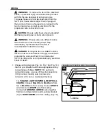
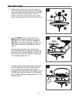
1A
FAN AND LIGHT CONTROLLED BY PULL CHAINS
BLACK
WHITE
GROUND/GREEN (BARE)
WHITE
BLUE
WHITE
FROM FAN
120 V Power
FROM
CEILING
FAN
GREEN
BLACK
GREEN
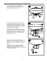
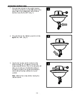
Choose wiring diagram (Fig. 1A, Fig. 1B or Fig. 1C)
that fits your situation and make appropriate wiring
connections as follows: [
NOTE:
For each wire
connection below, use one of the wire connectors
(CC) provided, making sure to screw wire
connector (CC) on in a clockwise direction.]
1A.
FAN AND LIGHT CONTROLLED BY PULL
CHAINS:
Connect
BLACK
and
BLUE
wire from
fan to
BLACK
wire from ceiling. Connect
WHITE
wire from fan to
WHITE
wire from ceiling.
Connect all
GROUND
(
GREEN
) wires together
from fan (on downrod (A) and mounting bracket
(C)) to
BARE
/
GREEN
wire from ceiling. (Fig. 1A)
1.
DANGER:
If using this fan in a DAMP location,
this fan must be connected to a supply circuit that is
protected by a Ground Fault Circuit Interrupter
(GFCI) to reduce the risk of personal injury, electrical
shock or death.


