background image

INITIAL INSTALLATION

7

 5. 

DOWNROD STYLE FAN MOUNTING

 1. 

 4.   

5

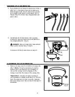
Loosen canopy mounting screws (L) in slotted holes 
in canopy (B) and remove the other two canopy 
mounting screws (L)--

save


canopy mounting screws 

(L) for later use

. Remove mounting bracket (C) from 

canopy (B). (Fig. 4A) 

Secure mounting bracket (C) to outlet box using 
screws, spring washers, and flat washers provided 
with the outlet box. (Fig. 4B)

*

Note: It is very important that you use the proper 

hardware when installing the mounting bracket (C) as 
this will support the fan.

IMPORTANT:

 If using the angle mount, make sure 

open end of mounting bracket (C) is installed facing 
the higher point of the ceiling.

4A

4B

L

L

C

C

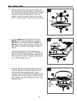
Remove motor screws (J) and lock washers (K) from 
underside of motor and save for blade arm (H) 
attachment later on. [If there are plastic motor blocks 
installed with the motor screws (J) and lock washers 
(K), discard the plastic motor blocks.] (Fig. 5)

Follow mounting instructions on pages 7 - 9 for 
“Downrod Style Fan Mounting” or proceed to pages 9 
and 10 for “Closemount Style Fan Mounting,” 
depending on mounting method (A or B) chosen in 
Step 2 on previous page.

B

K

J

M

N

A

D

Remove pin (M) and clip (N) from downrod (A). 
(Fig. 1A)

Partially loosen set screws in motor housing yoke 
at top of motor housing (D). (Fig. 1B)

*Helpful Hint

: Downrod style mounting is best 

suited for ceilings 8 ft. (2.44 m) high or higher. For 
taller ceilings you may want to use a longer 
downrod (not included) than the one provided. 
Angle style mounting is best suited for angled or 
vaulted ceilings. A longer downrod is sometimes 
necessary to ensure proper blade clearance.

Set

Screw

2

1A

1B

Содержание E-WCK44ABZ5LKS

Страница 1: ...ng parts Before returning to your retailer call or contact our customer service department at 1 800 527 1292 8 30 a m 5 00 p m CST Monday Friday ATTACH YOUR RECEIPT HERE Serial Number Purchase Date TI...

Страница 2: ...lified electrician or consult a do it yourself wiring handbook available at Lowe s if you are unfamiliar with installing electrical wiring Make sure the installation site you choose allows a minimum c...

Страница 3: ...ouse wire is larger than 12 gauge or there is more than one house wire to connect to the two fan lead wires consult an electrician for the proper size wire connectors to use To reduce the risk of fire...

Страница 4: ...ed 1 T 11 mm Lock Washer 1 preassembled U Compact Fluorescent Bulb 2 V Blade Plate 5 W Switch Housing Plate 3 Screw preassembled PART DESCRIPTION QUANTITY A Downrod 1 B Canopy 1 C Mounting Bracket 1 p...

Страница 5: ...2 compact fluorescent 13 watt max bulbs DANGER When using an existing outlet box make sure the outlet box is securely attached to the building structure and can support the full weight of the fan Fai...

Страница 6: ...2 Check to make sure blades G are at least 30 in from any obstruction Check downrod A length to ensure blades G are at least 7 ft above the floor Fig 3 3 ON OFF ON OFF 1 2 Determine mounting method t...

Страница 7: ...K from underside of motor and save for blade arm H attachment later on If there are plastic motor blocks installed with the motor screws J and lock washers K discard the plastic motor blocks Fig 5 Fo...

Страница 8: ...measure 8 in of lead wire and then cut the excess wire off with wire cutters not included Fig 4 NOTE If you do not cut back the lead wires Steps 4 and 5 are not necessary and you may proceed to Step 6...

Страница 9: ...DANGER Failure to align slot in ball with tab may result in serious injury or death 6 Continue to Wiring instructions on page 11 6 Remove canopy cover from bottom of canopy B Fig 1 Note It may be nece...

Страница 10: ...s will be located in one of the hardware packs Fig 2 2 D 2 Pull wires through hole in the middle of the canopy B and attach canopy B to motor housing D using the three screws and three lock washers re...

Страница 11: ...CHAINS BLACK WHITE GROUND GREEN BARE WHITE BLUE WHITE FROM FAN 120 V Power FROM CEILING FAN GREEN BLACK GREEN Choose wiring diagram Fig 1A Fig 1B or Fig 1C that fits your situation and make appropriat...

Страница 12: ...1B NOTE Black wire is hot power for fan Blue wire is hot power for light kit White wire is common for fan and light kit Green or bare wire is ground 1C FAN AND LIGHT CONTROLLED BY TWO WALL SWITCHES W...

Страница 13: ...range dimmer switch not included to control fan speed will cause a loud humming noise from fan To reduce the risk of fire or electrical shock do NOT use a full range dimmer switch to control fan spee...

Страница 14: ...go through holes in blade arm H Use three blade screws AA and three blade washers BB to secure blade plate V and blade arm H to blade G Do not tighten blade screws AA until each blade screw AA has bee...

Страница 15: ...g plate screws W that were removed in Step 4 on the previous page Tighten all switch housing plate screws W securely Fig 7 7 5 5 7 S T O F Threaded Rod Connect WHITE wire from light kit fitter O to WH...

Страница 16: ...to light kit fitter O Fig 10 Note Do not overtighten finial R as glass may crack or break 8 9 Rubber Washer P O R Q Install the two 13 watt max compact fluorescent bulbs U included Fig 8 CAUTION When...

Страница 17: ...oles in switch housing plate Re insert switch housing plate screws W that were previously removed Tighten all three switch housing plate screws W securely Fig 2 F D 3 Attach one of the pull chain exte...

Страница 18: ...hain in the middle is used to turn the light ON or OFF Fig 2 1 2 F 3 Use the fan reverse switch located on the switch housing F to optimize your fan for seasonal performance Fig 3 A ceiling fan will a...

Страница 19: ...DOWN for fan to function If the reverse switch is set in the middle position Fig 3C fan will not operate 3A 3B 3C At least twice each year lower canopy B to check downrod A assembly and then tighten a...

Страница 20: ...Blades G are loose 2 Blade arms H incorrectly attached 3 Unbalanced blades G 4 Fan not securely mounted 5 Fan too close to vaulted ceiling 6 Set screw s on motor housing yoke is are not tightened prop...

Отзывы: