background image

21

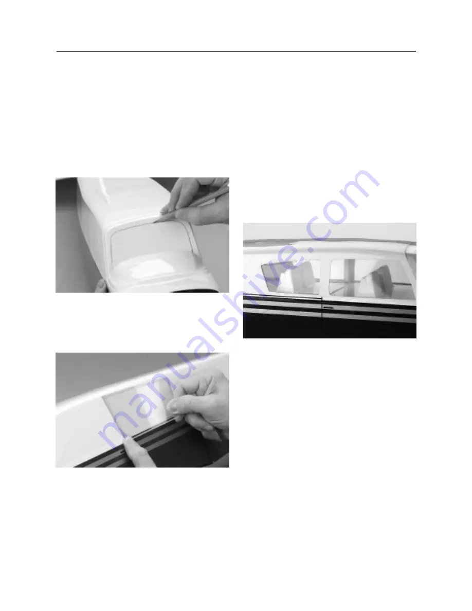
Step 3.

Trim out the opening of the front windshield. It helps to

use a felt tipped marking pen to outline the opening before
cutting. 

Note:

There are no scribe marks, so it’s important you mark
the opening before beginning. Again, use caution
when cutting the opening with your hobby knife. We
suggest the final trimming be done with a sanding
stick (medium/fine).

Step 4.

Using the side window openings as a guide, cut the

clear plastic sheet to make the side windows. Trial fit each
window to be sure they fit and can be installed from inside the
fuselage.

Step 5.

Apply canopy glue to the clear windows and carefully

install each into the interior of the fuselage. Masking tape can be
used to hold the side windows in place while the glue dries. Let
the glue dry completely before proceeding to the next step.

Note:

You may wish to only mount the windows on one
side, leaving one side open to give you access for
mounting the seats. Once the seats are installed, you
can then mount the remaining windows and front
windshield.

Step 6.

Remove any masking tape from the windows before

installing the seats. Trial fit the front and back seats in the
fuselage. The front seat backs should be approximately 2

′′

in

front of the back door trim of the fuselage. The rear seats will be
positioned behind the fuselage former and behind the front door
trim, close to where the front seats are located. There are two
balsa rails that can be used to help form a lip on which the rear
seat rests. Trimming of the plastic will be required to obtain the
proper fit. Once you are satisfied with the fit and location of each
seat, proceed to mix approximately 1/4 ounce of 12-minute
epoxy. Apply the epoxy to the rear seat rails first and mount the
rails. 

Once the rails are dry, proceed to mount the rear seat. 

Step 7.

Install the front seat next. It will be mounted on the

fuselage plywood doublers and some trimming may be required
to obtain a good fit. Once you are satisfied with fit and location,
proceed to epoxying the fuselage.

CONTINUED

Section 5: Assembling the Fuselage

Содержание Piper Cherokee

Страница 1: ...ve Hardware Included to Save Money Pre Covered Realistic Trim Scheme Semi Symmetrical Airfoil Specifications Wingspan 62 Length 45 1 2 Wing Area 720 sq in Weight Approx 6 6 25 lbs Recommended Engines 40 46 2 cycle 45 56 4 cycle PIPER WE GET PEOPLE FLYING TM TM ...

Страница 2: ...inging the Vertical Horizontal Stabilizers 27 Section 8 Installing the Control Horns 28 Section 9 Assembling and Installing the Fuel Tank 30 Section 10 Installing the Landing Gear 33 Section 11 Installing the Nose Gear 35 Section 12 Assembling and Mounting the Wheel Pants 36 Section 13 Installing the Engine 38 Section 14 Installing the Cowling 39 Section 15 Installing the Radio 41 Section 16 Insta...

Страница 3: ... prior to flying the Piper Cherokee Warning An R C aircraft is not a toy If misused it can cause serious bodily harm and damage to property Fly only in open areas preferably AMA Academy of Model Aeronautics approved flying sites following all instructions included with your radio and engine Additional Equipment Required Radio Equipment 4 Channels minimum 4 Standard Servos Standard 450 650 mAh Rece...

Страница 4: ...Medium Phillips screwdriver Z bend pliers Pliers Small round file Razor saw Moto Tool with sanding drum Hobby knife with 11 blade Mixing stick Epoxy brush 90 degree triangle File Sanding stick medium or fine Medium sandpaper Masking tape Straight edge Measuring device e g ruler tape measure Scissors Paper towels Wax paper Rubbing alcohol Felt tipped pen Fuel tubing Clips e g clothespins binder cli...

Страница 5: ... Other 1 Pushrod accessories 9 Foam wheels 3 2 1 8 plywood die cut parts 10 Fuel tank and hardware 3 Main landing gear 11 Seats not shown 4 Nose landing gear 12 Cowling not shown 5 Spinner 13 Windshield 6 Hardware bag 14 Clear plastic for windows not shown 7 Plastic parts tree 15 Trim sheet not shown 8 Wheel pants 3 not shown 16 Motor mount 13 3 10 6 5 7 16 1 4 2 9 A C B E D ...

Страница 6: ...6 Field Equipment Required Airplane Fuel Propeller Glow Driver Glow Plug Wrench Glow Plug Manual Fuel Pump ...

Страница 7: ...7 Optional Field Equipment Starter 12V Sealed Battery 4 Way Wrench Field Box Cleaner Towels Extra Glow Plugs Misc Tools After Run Fuel Power Panel 64 Rubber Bands ...

Страница 8: ...on Additionally apply a small amount of epoxy to the top and bottom half of each hinge Insert the hinges into the aileron until the hinge line is even with the leading edge of the aileron Note Do NOT apply any epoxy into the aileron torque rod hole at this time Step 4 Lightly coat both ends of the aileron with epoxy this will prevent the aileron from becoming fuel soaked Step 5 Wipe off any excess...

Страница 9: ...ned and that the aileron torque rod presses into its respective hole in the aileron The use of a piece of wax paper between the torque rod and wing will prevent epoxy from adhering to the wing The gap between the aileron and the wing should remain a constant 1 16 or as tight as possible without restricting the movement of the aileron Step 8 Carefully wipe off any excess epoxy using a paper towel a...

Страница 10: ...ea which has the slight V shape Step 3 Clamp the three joiners together using clothespins or clips Make sure the joiners remain aligned and the clamps are firmly attached Step 4 Wipe away the excess epoxy using a paper towel and rubbing alcohol Be careful not to disturb the alignment of the wing joiners Note Any excess epoxy should be removed before it cures Section 2 Joining the Wing Halves Right...

Страница 11: ...e opposite wing tip should be exactly 1 3 4 from the surface see illustration below If necessary sand the dihedral brace until this is achieved Step 9 Place the wing halves on the flat surface so the white side bottoms are facing downward Using a felt tipped pen place a mark at the leading edge and trailing edge of the servo bay on each wing half These marks will be utilized as a guide when cuttin...

Страница 12: ...wing joiner cavity up to the center line making sure that the V of the dihedral brace is positioned correctly Step 13 Apply a generous amount of epoxy into the wing cavity of the other wing half Step 14 Smear epoxy on all sides of the exposed area of the dihedral brace and uniformly coat both wing roots with epoxy CONTINUED Section 2 Joining the Wing Halves ...

Страница 13: ...Apply masking tape to the wing joint to hold the wing together securely while the epoxy cures Place the wing on a large flat surface With one wing panel lying flat on the surface the opposite wing tip should be propped up exactly 1 3 4 from the surface Allow the wing joint to dry overnight Note It is a good idea to place a sheet of waxed paper under the center joint of the wing so that any excess ...

Страница 14: ...o pieces of masking tape ensuring that the alignment is not disturbed Step 5 Using a felt tipped pen trace around the outside upper and lower parallel edges of the servo tray These marks will serve as the guides for cutting the servo tray support slots later in this section Additionally place a mark along each of the outside vertical edges of the tray These marks will be the outer edges of the ser...

Страница 15: ...o the slots It may be necessary to enlarge the slot slightly to accommodate the support Step 9 Using the sharp hobby knife carefully cut through the balsa wood and the covering along the lines that were drawn in Step 6 of this section Remove the excess balsa from the hole Step 10 Trial fit the aileron servo into the servo tray Also trial fit the servo into the hole cut in the wing in Step 9 to see...

Страница 16: ...ke sure the aileron servo support and the servo tray remain perpendicular to one another Allow the epoxy or CA to dry completely before proceeding to the next step Step 13 Mix a small amount of 6 minute epoxy to glue the servo tray into the wing Using an epoxy brush apply the epoxy to the aileron servo supports Insert the assembled unit into its receptacle in the wings Remove any excess epoxy with...

Страница 17: ...ap the tape completely around the wing joint seam to the rear of the servo tray Gently pulling on the tape while pressing it down onto the wing will provide a smooth seam Cut any excess tape with a pair of scissors Note You will install the aileron servo in Section 15 CONTINUED Section 3 Installing the Aileron Servo Tray ...

Страница 18: ...ng hold down holes are located toward the rear of the fuselage wing opening Note that the wing blind nuts are already installed You will not have to do anything with these holes other than note their location Step 4 The two wing hold down bolt holes are located near the trailing edge of the wing You will need to trim away the covering with your hobby knife Using a 1 4 drill bit drill out the two h...

Страница 19: ...e This point will be the reference point to determine the wing alignment in the next step Step 7 Bolt the wing to the fuselage Turn the aircraft upside down and using a ruler hold one end of the ruler on the fuselage reference point you made and the other end of the ruler to one of the wing panel ailerons Measure the distance Next measure the distance of the other wing panel using the reference po...

Страница 20: ...ndows Examine the fuselage top carefully Note the window opening scribe marks on each side of the fuselage top Trim out the openings with a sharp hobby knife Caution Use care to cut the opening Final trim of the opening can be done with a sanding stick medium fine Fuselage Plywood servo tray Front windshield Clear plastic sheet for side windows Motor mount Motor mount screws 4 Seats Canopy glue e ...

Страница 21: ... seats Once the seats are installed you can then mount the remaining windows and front windshield Step 6 Remove any masking tape from the windows before installing the seats Trial fit the front and back seats in the fuselage The front seat backs should be approximately 2 in front of the back door trim of the fuselage The rear seats will be positioned behind the fuselage former and behind the front...

Страница 22: ...nd apply it to the servo tray and fuselage where the servo tray will rest Allow the epoxy to cure completely before proceeding Step 8 Trim the front windshield and trial fit it to the fuselage Once you are satisfied with the fit use canopy glue to install the windshield Use masking tape to hold the windshield in place while the glue dries Let the glue cure completely Note Included in your Cherokee...

Страница 23: ... useful to make the final shaping of the opening Trial fit the horizontal stabilizer in the opening Step 2 Trim away the opening for the vertical stabilizer located on the top rear of the fuselage Again use caution during this process Use a sanding stick to make the final adjustments to the opening Trial fit the vertical stabilizer in the opening Step 3 Smooth any rough edges with a sanding stick ...

Страница 24: ...the fuselage to the leading edge on each side of the horizontal stabilizer A piece of masking tape positioned at the centerline of the fuselage top can be used as the reference point The distance must be equal on both sides If not adjust the stabilizer accordingly until the measurements are the same Note It is important to be sure the horizontal stabilizer is correctly aligned Step 7 When you are ...

Страница 25: ... position it in the approximate location Adjust the alignment as described in Step 6 of this section Step 11 Wipe off any excess epoxy using a paper towel and rubbing alcohol Allow the epoxy to cure fully before proceeding to the next step Step 12 Trial fit the vertical stabilizer into position Using a pencil trace around the vertical stabilizer where it meets the fuselage Again the pencil should ...

Страница 26: ...lizer Do not apply epoxy to the rudder itself Step 15 Insert the vertical stabilizer into the fuselage ensuring that it is seated properly on the horizontal stabilizer Using a 90 degree triangle check to make sure that the vertical stabilizer is perpendicular to the horizontal stabilizer Step 16 Wipe off any excess epoxy with a paper towel and rubbing alcohol being careful not to disturb the align...

Страница 27: ...leading edge of the rudder Note It sometimes helps to roughen the hinge surface with a sanding stick so the epoxy will have a better grip Step 4 Apply epoxy to the remaining half of each hinge and into the hinge slots in the vertical stabilizer as well Replace the rudder into the vertical stabilizer Step 5 Carefully wipe away the excess epoxy using a paper towel and rubbing alcohol Step 6 Repeat t...

Страница 28: ...rk made in the previous step Using a felt tipped pen mark the hole position of the control horn Step 3 Remove the control horn and drill two 1 16 holes through the elevator as marked Step 4 Attach the elevator control horn using the hardware provided two screws and backplate and fasten in place using a Phillips screwdriver Control horns 2 Control horn backplate 2 Control horn screw 4 Fuselage Dril...

Страница 29: ...ve as the center for the rudder control horn Step 6 Center the control horn over the mark you ve just made and using a felt tipped pen or pencil mark the mounting hole locations through both holes onto the rudder Step 7 Drill these holes with a 1 16 drill bit and install the rudder control horn using the two screws and backplate provided CONTINUED Section 8 Installing the Control Horns ...

Страница 30: ...is for use as an optional fill tube Step 3 Locate the longer aluminum tube and bend it with your fingers as shown This tube will be the fuel tank vent tube It will be connected to the pressure fitting of your motor s muffler when the engine is plumbed in Section 17 Section 9 Assembling Installing the Fuel Tank Fuel tank Fuel tubing not supplied Fuel clunk Aluminum tube short pickup Aluminum tube s...

Страница 31: ...rear inside the tank of the stopper Also note that the stopper fits over the outside of the tank neck Step 5 Slide the two black plastic caps over the aluminum tubes as shown noting the orientation of the caps The small inside cap and the bumps face away from the black rubber stopper The large outside cap and the bump go away from the black rubber stopper Step 6 Locate the silicone fuel tubing and...

Страница 32: ...fuel tank clunk does not touch the rear of the fuel tank If it does simply cut a small portion of the silicone fuel tubing until the clunk no longer reaches the rear of the tank Step 9 Place the foam fuel tank collar around the neck of the fuel tank and press the fuel tank firmly against the firewall until the stopper inserts into the hole in the firewall The plastic cap will be nearly flush with ...

Страница 33: ...ood from becoming fuel soaked Step 3 After the epoxy has cured completely place the main landing gear into the channel in one of the wing panels as shown Step 4 Remove two landing gear straps from the plastic parts tree and place them across the landing gear strut Using a pencil mark the location of the four landing gear mounting strap holes Main landing gear 2 Landing gear straps nylon 4 2 6mm se...

Страница 34: ...ed in the previous step Step 6 Reposition the landing gear and straps as described previously Using the four 2 8mm self tapping screws located in the hardware bag fasten the landing gear to the bottom of the wing as shown Step 7 Repeat the process to mount the second main landing gear in the wing CONTINUED Section 10 Installing the Landing Gear ...

Страница 35: ... gear assembly up through the nose gear mount until the coil is just below the bottom of the firewall Slide the nose gear control horn on the nose gear Position it so the angled parts of the horn are closest to the firewall One of the nose gear control horns will be trimmed off later Step 4 Adjust the nose gear control horn until the arm is parallel with the firewall Apply Blue Locktite 242 to a 3...

Страница 36: ... each side Use these dimples as a guide to drill a hole completely through each of the wheel pants using a 5 32 drill bit Step 3 Insert one of the 2 foam wheels into the left wheel pant aligning the landing gear hole in the foam wheel with the one drilled in the previous step Section 12 Assembling Mounting the Wheel Pants Wheel pants 3 2 foam wheels 3 Wheel collars with screws 3 Wheel pant decal s...

Страница 37: ...ld be pressed against the wheel pant so that it remains seated in the landing gear strut Apply Blue Locktite 242 to the wheel collar screw and securely tighten It may be necessary to gently squeeze the wheel pant when tightening the wheel collar screw Note The wheel must rotate smoothly Step 5 Repeat this procedure for the right side of the landing gear and for the nose gear CONTINUED Section 12 A...

Страница 38: ...unting bracket holes Press one of the 4mm nuts into the corresponding receptacle on the bottom of the motor mount Do not use Blue Locktite 242 at this time as you will need to make minor adjustments to the motor position when you are measuring and mounting the cowling It may be necessary to mount and remove the muffler as you make trial fittings of the cowl The spinner is mounted after the cowl ha...

Страница 39: ...l be glued later with CA For now trim so you have at least 1 4 of material completely around the lip portion of the blue cowl If there is paint on the lip sand it off so the CA will adhere Trial fit the cowling to your engine cylinder head to determine how much material to trim away in that portion for the engine cylinder head Trim using your scissors Rough edges can be smoothed with a sanding sti...

Страница 40: ... then mark four screw hole locations on each side of the cowl We would suggest two screws in the upper cowl half and two screws in the lower half on both sides of the cowling Note The firewall has a plywood balsa lip to which the cowling will be attached Step 6 Final trim of the cowl will depend on the type of engine and the location of the spring of the nose wheel in relation to the cowl Step 7 A...

Страница 41: ...g the four screws included with the servo Rudder Elevator and Throttle Servo Installation Step 4 Install the rubber grommets and eyelets in the three remaining servos Position the servos in the fuselage servo tray as shown Important Note Note the location of the output horns Using a pencil mark the 12 servo mounting hole positions 4 channel radio system with four servos and hardware not included F...

Страница 42: ...ompartment that is in front of the servo tray Cut out another layer of foam that is identical in size however cut an opening in the center of this foam so it will accept the receiver battery pack Place another solid layer of foam on top of this layer Cut another layer of foam to accept the receiver The final layer of foam should be solid Step 7 Place the layers of foam with the battery and receive...

Страница 43: ...tach the switch plate from the receiver switch harness Center the switch plate over the hole which was cut in the previous step Using a felt tipped pen or pencil mark the screw hole on either end of the switch plate Step 10 Remove the switch plate from the fuselage Using a 1 16 drill bit drill the two mounting holes as marked Step 11 Reposition the switch plate as shown and place the switch on the...

Страница 44: ...vator and rudder pushrods Step 3 Screw a clevis onto the threaded end of each rod Step 4 Center the servo horn and install the Z bend into the outermost hole on either side of the servo arm Step 5 Attach the clevises onto their respective aileron horns Note It is a good idea to place a piece of fuel tubing over the clevises This will provide extra insurance against the clevises accidentally coming...

Страница 45: ... threaded end This rod will be used to attach the clevis to the rudder control horn Step 10 Using needle nose pliers bend a 90 degree angle 1 4 from the unthreaded end of the threaded rod Step 11 Insert the 90 degree bend into the hole of the balsa dowel and saturate the balsa with thick CA glue where the rod contacts the balsa Step 12 Slide a piece of heat shrink tubing over the end of the balsa ...

Страница 46: ...tep 18 Screw on a clevis 12 complete turns Fasten the clevis in the third hole from the inside of the rudder control horn Note It s a good idea to place a piece of fuel tubing over the clevis as extra insurance to prevent the clevis from accidentally coming open Step 19 Center the rudder servo and using a felt tipped pen place a mark on the unthreaded end of the rudder pushrod where is passes the ...

Страница 47: ...pen Step 26 Center the elevator servo and using a felt tipped pen place a mark on the pushrod where it passes the respective servo arm Step 27 Using Z bend pliers make a Z bend at the marked location on the rod Cut off the excess rod Throttle Linkage Step 28 Locate one of the longer 17 3 4 threaded rods and one clevis Step 29 Screw the clevis onto the threaded end of the rod approximately 12 turns...

Страница 48: ...le in the fuselage Step 38 Screw on a clevis 12 full turns Fasten the clevis in the outermost servo arm hole opposite the rudder servo Z bend Step 39 Be sure that the rudder servo is centered Using a felt tipped pen place a mark on the unthreaded end of the steering pushrod where it passes the nose wheel steering arm Step 40 Using a Z bend pliers make a Z bend at the marked location on the rod Cut...

Страница 49: ...nt tube from the fuel tank to the pressure fitting or nipple on the muffler Step 3 The remaining tube should be attached to the carburetor fuel inlet nipple Section 17 Plumbing the Engine Fuselage Engine Fuel tubing Scissors or sharp hobby knife to cut tubing Parts Needed Tools and Adhesives Needed ...

Страница 50: ...19 Balancing the Cherokee An important part of preparing the aircraft for flight is properly balancing the model Don t inadvertently neglect this step The Cherokee is very stable and has a wide range of C G Center of Gravty With the various brands of radios and engine equipment available the C G can be between 3 1 4 to 4 back from the the leading edge of the wing If your Cherokee does not balance ...

Страница 51: ...clevis is securely snapped into position Step 3 Check that all servo horn screws are tight Step 4 Charge the transmitter and receiver battery per the instructions included with your radio system Step 5 Read and follow all the instructions included with the engine and follow the recommended break in procedure ELEVATOR ELEVATOR AILERON AILERON AILERON THROTTLE 1 16 CARBURETOR RUDDER RUDDER Pre Fligh...

Страница 52: ...at all controls aileron elevator throttle rudder move in the correct direction Step 3 Be sure that your batteries are fully charged per the instructions included with your radio Adjusting the Engine Step 1 Completely read the instructions included with your engine and follow the recommended break in procedure At the field adjust the engine to a slightly rich setting at full throttle and adjust the...

Страница 53: ...t operate models with metal bladed propellers or with gaseous boosts in which gases other than air enter their internal combustion engine s nor will I operate models with extremely hazardous fuels such as those containing tetranitromethane or hydrazine 9 I will not operate models with pyrotechnics any device that explodes burns or propels a projectile of any kind including but not limited to rocke...

Страница 54: ... Copyright 1998 Horizon Hobby Distributors Inc ...

Отзывы: