28
Step 3.
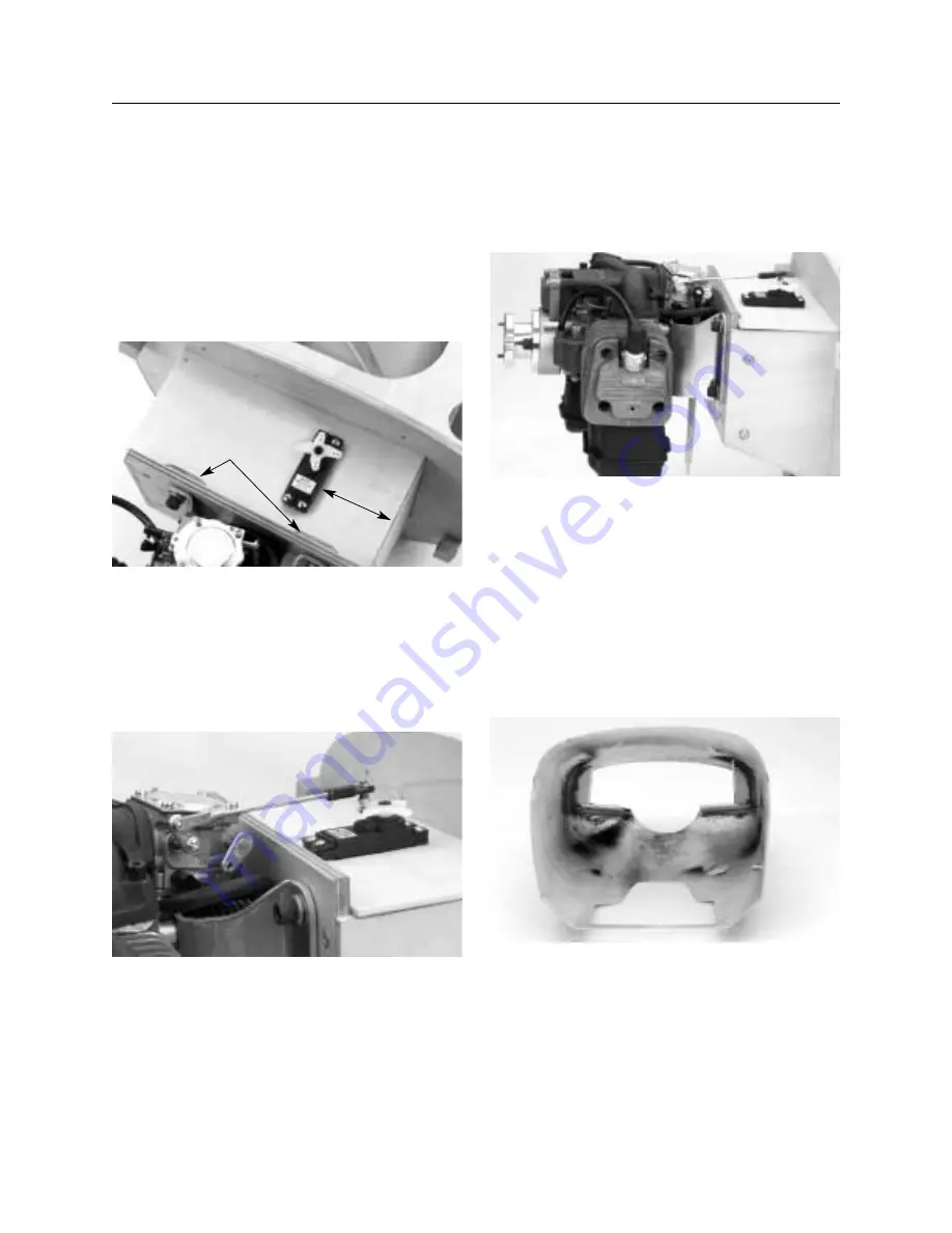
If using the GT-80 (or 445) the throttle servo is position
as shown in the top of the engine box. Using a pen, mark the
opening for the servo 2
5
/
8
" from the left side of the top plate.
Note that the top plate is tapered to accommodate the firewall
right thrust angle. Be sure to mark the servo opening in the
correct position. Use a jig saw to cut out the servo opening in the
top plate. It will be necessary to cut clearance openings for the
blind nuts in this plate.
Step 4.
Using 5 minute epoxy glue the top plate in place.
Mount the throttle servo using the hardware included with the
servo. Using a 4-40 threaded rod, a solder link, and a 4-40 ball
link, make up the throttle pushrod to the appropriate length.
Securely solder the solder link in place and attach the 4-40 ball
link to the pushrod and the servo arm.
Step 5.
If using a Zenoah GT-80, attach a 4-40 x 6" threaded
rod to the choke lever using a 4-40 ball link. The 4-40 rod runs
down through the engine mount and exits the bottom of the cowl.
Step 6.
Run the fuel lines from the pick up in the tank to the
carburetor and run the vent line out the bottom of the fire wall.
We recommend using a fuel dot and a kill switch mounted in the
cowl for convient fueling and safety.
Step 7.
Using a Moto-tool and cut off wheel and drum sander,
cut an air outlet in the bottom of the cowl as shown. The
aproxamate size should be 5" x 5". It may also be necessary to
cut out an area for the mufflers to exit depending on the mufflers
and engine you use.
Step 8.
Mount the fuel dot and kill switch in the cowl in a
convienent location then mount the cowl in place using the
included 4-40 hardware.
Section 11: Mounting the Engine and Cowl
CONTINUED
Clearance Openings
2
5
/
8
"


