HAMWORTHY HEATING LTD
44
FLEET H series
500001212/F
forward.
With the heat exchanger removed from the appliance,
remove the plastic sump from the heat exchanger sealing
plate and withdraw the sump away from the sealing plate.
The heat exchanger fin matrix is now accessible and the
flue ways can be cleaned using a 25mm wide * 1mm
thick* 400mm strip to clean between the fins, ensuring
that any debris is collected .
When clean, re-assemble in reverse order using new
seals /gaskets where appropriate.
Re-fit the pump and return pipe assembly. Open the
isolating valve and test all joints broken or disturbed for
water soundness.
Re-fit the burner assembly.
Test all gas joints broken
or disturbed for soundness before firing
.
Refer to
Section 8 Commissioning The Boiler
.
11.0 REPLACEMENT OF FAILED COMPONENTS
There are a number of components listed below which
can be replaced simply and quickly by following the given
procedure. In each case the operation of each replaced
component must be checked by carrying out the
appropriate part of the commissioning procedure. See
Section 8: COMMISSIONING & TESTING.
Note:- Isolate all electrical supplies to the boiler
module before opening the front cover and
commencing any servicing or component exchange
procedure. Turn off the gas at the service valve.
11.1 HT Electrode and Flame Probe -
Part nos. 533805029 & 533805021
Note:- The electrode and flame probe ceramics are
very fragile.
Disconnect the HT cable from the electrode. Remove the
2 M4 screws securing the electrode to the heat
exchanger and carefully remove the electrode and it’s
gasket. Check the condition of the ceramic, wires and the
spark gap. Adjust if necessary. In replacing the electrode,
fit a new gasket and take care when feeding the wires
through the heat exchanger aperture. Carefully re-
connect the HT cable to the electrode.
Disconnect the cable from the flame probe. Remove the
1 M4 screw securing the probe to the heat exchanger
and withdraw the probe. Check the condition of the
ceramic and wire. In replacing the probe fit a new gasket
and refit the cable.
To check the position of the electrode and probe in
relation to the burner, remove the burner and refer to
Figures 10.2. , 10.2.1 & 10.2.2
11.2 Flow / Return sensor - part no. 533901549
Note: The flow/return sensors are immersed in the
water circuit. To remove/replace will require the heat
exchanger to be drained.
The two identical sensors are located in the return elbow
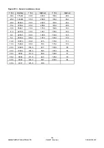
and flow elbow. Prior to removal, check the resistance of
the sensor against
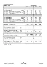
Figure B 1.3
In refitting the sensor, a
sealant will be required on the threads. Check for water
soundness before firing the boiler.
11.3 Flue Gas sensor - Part no. 533901549
The flue gas sensor is located in the flue elbow. Prior to
removal, check the resistance of the sensor against
Figure B 1.3
In refitting the sensor, a sealant will be
required on the threads. Check for soundness of the joint
when firing the boiler.
11.4 Temperature Limiter (Limit Stat)
Part no. 533901583
The limit stat is a bi-metallic disc type located on the top
of the last heat exchanger section, secured by a spring
clip. The thermostat can be accessed through the rear
panel. Remove the thermostat from the clip and
disconnect the electrical connections.
Beware the
terminals are 230v! When refitting the control ensure
that it is fully engaged in the clip.
11.5 Water Flow switch - Part no. 533901548
Note: The flow is immersed in the water circuit. To
remove/replace will require the heat exchanger to be
drained.
The water flow switch is located in the return pipe on the
pump inlet. Undo the union and carefully withdraw the
switch assembly from the pipe. The switch consists of a
magnetic reed switch providing open or closed circuit. In
fitting a replacement switch ensure that a new sealing
gasket is used.
11.6 Gas Valve
Part no. 533903040 - F40 - F70H
Part no. 533903044 - F85 - F150H
All models -
isolate the gas supply using the valve
located in the bottom left hand corner.
Disconnect the electrical lead and pressure sensing tube.
Models F40 H, F50H, F60H& F70H
Remove the 4 - M4 screws securing the inlet elbow to the
gas valve.
Support the weight of the valve and remove the 3 - M4
screws securing the valve to the venturi.
Replace the gas valve using new seal / ‘o’ ring.
Models F85H/F100H/F125H & F150H
Remove the 4 - M5 screws securing the inlet fitting to the
gas valve.
Support the weight of the valve and remove the 4 - M5
screws securing the gas valve and spacer assembly to
the venturI. Remove the 4 - M5 screws securing the
spacer to the gas valve.
Replace the gas valve using new ‘o’ rings.
All models - reassemble in reverse order and check all
joints for gas soundness.
11.7 Fan
Part no. 533901376 - F40 - F70H
Part no. 533704009 - F85 - F125H
Part no. 533704010 - F150H
To remove the fan it is preferable to remove the complete
fan, gas valve and venturi assembly.
To improve access, remove the casing top panel.
Disconnect the electrical lead and pressure sensing tube
from the gas valve.
Disconnect the two electrical plugs (power supply and
speed control signal) from the fan motor.
Disconnect the gas supply from the inlet to the gas valve.
Loosen the worm drive securing the air inlet duct to the
venturi.
Содержание F100H
Страница 2: ......
Страница 35: ...HAMWORTHY HEATING LTD 29 FLEET H series 500001212 F Figure 8 2 1 3 Operation and display philosophy...
Страница 44: ...HAMWORTHY HEATING LTD 38 FLEET H series 500001212 F Figure 8 3 11 Operating phases...
Страница 75: ...HAMWORTHY HEATING LTD 69 FLEET H series 500001212 F NOTES...
Страница 77: ...Please complete the information on the Registration Card cut out and return to Hamworthy Heating Ltd...
Страница 78: ......
Страница 79: ......


