HAMWORTHY HEATING LTD
11
FLEET H series
500001212/F
4.3 Flue Terminal Locations
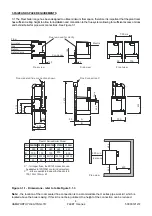
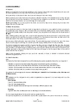
The diagram below details the minimum spacing requirements for flue terminals from other building features when
using the concentric and twin duct flue systems (C13, C33, C53 & B23)
It is recommended that air supply inlet terminals are positioned no closer than 300mm to any flue terminal when
using C53 twin pipe flue systems. Air supply inlets should preferably be positioned lower than flue terminals.
Figure 4.3.2
Dim
Terminal Position
Min Distance
(mm)
A
Directly below an opening, air brick, opening window etc
300
B
Above an opening, air brick, opening window etc
300
C
Horizontally to an opening, air brick, opening window etc
300
D
Below gutters, soil pipes or drain pipes
75
E
Below eaves
200
F
Below balconies or car port roof
200
G
From a vertical drain pipe or soil pipe
150
H
From an internal or external corner
300
I
Above ground roof or balcony level
300
J
From a surface facing the terminal
600
K
From a terminal facing the terminal
1200
L
From an opening in the car port (e.g. door, window) into the dwelling
1200
M
Vertically from a terminal on the same wall
1500
N
Horizontally from a terminal on the same wall
300
O
From the wall on which the terminal is mounted
N/A
P
From a vertical structure on the roof
N/A
Q
Above intersection with roof
N/A
Note: Flue Installation should comply with BS5440 Part 1
Содержание F100H
Страница 2: ......
Страница 35: ...HAMWORTHY HEATING LTD 29 FLEET H series 500001212 F Figure 8 2 1 3 Operation and display philosophy...
Страница 44: ...HAMWORTHY HEATING LTD 38 FLEET H series 500001212 F Figure 8 3 11 Operating phases...
Страница 75: ...HAMWORTHY HEATING LTD 69 FLEET H series 500001212 F NOTES...
Страница 77: ...Please complete the information on the Registration Card cut out and return to Hamworthy Heating Ltd...
Страница 78: ......
Страница 79: ......

