24
11.
LCOS-SLM operation check
In this chapter, you run LCOS-SLM and display the attached phase image to confirm that LCOS-SLM is
operating correctly.
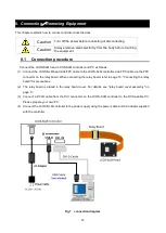
1. Construct the optical system.
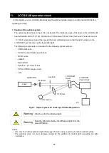
The optical system shown in Fig. 20 is constructed. The incidence angle of the laser on the LCOS-SLM
head should be within 5° (P. 23). Position the CCD camera 100 mm from the Fourier Transform lens at
f = 100 (Fourier plane). Adjust the special filter and collimating lens so that the light incident on the
LCOS-SLM head becomes perfectly parallel light.
The following components are required for the following optical systems.
・
LCOS-SLM suite
・
PC (DVI output: Desktop preferred)
・
DVI-D cable
・
LASER
・
Special filter
・
Aperture... φ 12 mm or less
・
CCD or CMOS image sensor
・
Lens
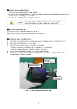
Fig.20
Optical system for checking LCOS-SLM operation
Warning
Watch out for the reflected light.
Warning
Note the light reflected by the diffracted light from the
pixel diffraction.
Advice
・
Use only horizontally polarized light (See page 21) when using a grazing incidence optical system.
・
The warranty does not cover damage caused by the addition of incident light exceeding the light
resistance.
Spatial filter
CCD camera
f=100mm
LCOS-SLM
driver circuit
LCOS-SLM
Head
Aperture
f=400mm
PC
Laser

