


CONNECT SERIES SERVICE MANUAL
ENGLISH
Contents
Foreword
Thank you for choosing GE Appliances Connect Series heat pumps.. Please read this manual carefully in
order to properly install the equipment and maximize customer satisfaction.
This manual specifies safe operation requirements from perspectives of product introduction, control,
troubleshooting and maintenance, as well as basic principles and implementation methods. Professional
operators must abide by relevant national (local) safety requirements and technical specifications set
forth in this manual during operations; otherwise, the air conditioning system may fail or be damaged, and
personnel safety may be compromised.
Please read this instruction manual before operating this heat pump.
Please read this manual before installing this heat pump.
Before repairing the air conditioner, please first read the technical service manual.
Safety Notifications ......................................................................................................................................................1
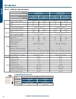
Introduction .................................................................................................................................................................. 3
Lists of Units............................................................................................................................................................................................................... 3
Specifications ............................................................................................................................................................................................................4
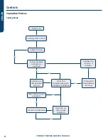
Controls .........................................................................................................................................................................6
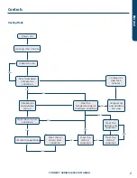
Operation Modes ......................................................................................................................................................................................................6
Control Modes ........................................................................................................................................................................................................... 8
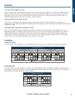
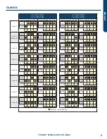
Functions .....................................................................................................................................................................................................................9
Troubleshooting ......................................................................................................................................................... 14
Wiring Diagrams ..................................................................................................................................................................................................... 14
PCB Layout ................................................................................................................................................................................................................18
Indoor Unit LED Indicators .................................................................................................................................................................................27
Outdoor Unit Error Codes...................................................................................................................................................................................27
Troubleshooting ......................................................................................................................................................................................................28
Failures Not Caused by Errors ......................................................................................................................................................................... 42
Maintenance ................................................................................................................................................................43
System Diagram ..................................................................................................................................................................................................... 43
System Evacuation ............................................................................................................................................................................................... 43
Refrigerant Charging ........................................................................................................................................................................................... 44
Maintenance of Major Components ............................................................................................................................................................... 45
Removal of Major Components ........................................................................................................................................................................52
Exploded View and Parts Lists ........................................................................................................................................................................ 86
Appendices .................................................................................................................................................................93
Temperature Sensor Temperature/Resistance/Voltage Lists ...............................................................................................................93
15 K
Ω
Temperature Sensors (including ODU temperature sensors) ............................................................................................93
20 K
Ω
Pipeline Temperature Sensors (including temperature sensors for defroster, IDU and ODU pipes) ................95
50 K
Ω
Discharge Temperature Sensors (including discharge air temperature sensor) .......................................................97
Refrigerant R-410A Temperature/Pressure List ........................................................................................................................................ 99
Operation Tools ......................................................................................................................................................................................................101
Содержание GE Connect Series
Страница 17: ...CONNECT SERIES SERVICE MANUAL 15 ENGLISH Troubleshooting Model AUH4860ZGDA ...
Страница 28: ...CONNECT SERIES SERVICE MANUAL 26 ENGLISH Troubleshooting AUH4860ZGDAA ...
Страница 90: ...CONNECT SERIES SERVICE MANUAL 88 ENGLISH Maintenance AUH4860ZGDA ...
Страница 92: ...CONNECT SERIES SERVICE MANUAL 90 ENGLISH Maintenance IDU Exploded View and Parts Lists UUY24ZGDAA UUY36ZGDAA ...