


x
V.
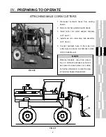
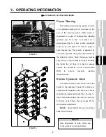
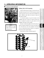
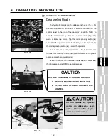
OPERATING INFORMATION
TASSELTROL
®
CONTINUED
TASSELTROL
®
CONTINUED
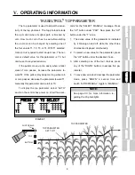
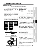
To use the control box with its normal parameter setting,
use the following procedures. To adjust the given parame-
ters, see pages XX-XX.
1. From the operator’s seat, turn the ignition to the “ON”
position.
2. Turn the control box power switch to the “ON” position.
3. Turn the “AUTO/MANUAL” switch to “MANUAL.” At this
time the display will read “MANUAL” in addition to other
information identifying the control box.
4. Press the individual row switches for up and down
movement. An arrow in the display will indicate direction
of each lift assembly. “P” indicates pressure - “UP” on-
ly.
5. If the “AUTO/MANUAL” switch is left in the “AUTO” po-
sition when the unit is first started, the display will tell
you to select “MANUAL.” After you have selected
“MANUAL” switch back to the “AUTO” position.
6. To raise and hold one or more units during operation,
press the desired “UP” switch, select “MANUAL” and
back to “AUTO.” This will hold the unit up in position. To
re-activate the lift, switch to “MANUAL” and back to
“AUTO.”
7. To override the system, press the desired “UP” switch
to raise the attachment. When the switch is released,
the system will go back into the “AUTO” mode.
8. If the ignition is left on and the “AUTO/MANUAL” switch
is left in the “AUTO” position, the down coils on the
electro-hydraulic valve will lose power after 45 seconds.
To re-activate, move the “AUTO/MANUAL” switch from
“AUTO” to “MANUAL” and back to “AUTO.”
9. The control box is set up with a feature so that if a unit
loses contact during operation in the “AUTO” mode, the
unit will automatically rise. If this should happen, switch
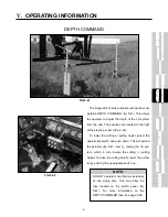
OPERATING THE TASSELTROL
®
/LS CONTROL
FIG 5.28
1
LIFT
ON
OF
F
AUTO
MA
N.
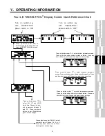
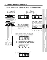
DEPTH CONTROL
TASSELTROL / LS
SYSTEM 12
S. I. E. level 2.1
SELECT MANUAL
CABLE BOX sn: C98ØØ9
PAR=s B1 R2 T3 L8 DØØ
5
LIFT
6
LIFT
2
LIFT
3
LIFT
4
LIFT
ON AUTO
FIG 5.29
UP
FIG 5.27
Содержание 204
Страница 133: ...x IX TROUBLE SHOOTING TASSELTROL LS SYSTEM ELECTRICAL CONTINUED FIG 9 1 1 2...
Страница 134: ...x IX TROUBLE SHOOTING NOTES...
Страница 140: ...138 NOTES...
Страница 141: ...x...


