


x
IV.
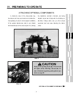
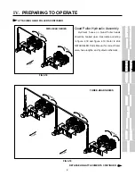
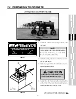
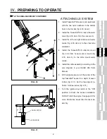
PREPARING TO OPERATE
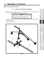
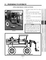
10 – 12 ROW OUTRIGGER ASSEMBLY
ATTACHING EQUIPMENT CONTINUED
2. Attach left and right outrigger (fig. 4.12, item 3) with supplied hardware. Refer to 204 DETASSELER
OPTION Parts Manual.
3. Attach outrigger support rods.
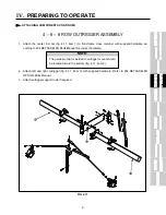
1. Attach the center tool bar (fig. 4.12, item 1) to front frame cross member with supplied hardware ac-
cording to 204 DETASSELER Parts Manual for correct hardware.
NOTE:
The guide pin that is welded to outrigger mount should
be located toward the bottom (fig. 4.12, item 2).
FIG 4.12
2
1
3
Содержание 204
Страница 133: ...x IX TROUBLE SHOOTING TASSELTROL LS SYSTEM ELECTRICAL CONTINUED FIG 9 1 1 2...
Страница 134: ...x IX TROUBLE SHOOTING NOTES...
Страница 140: ...138 NOTES...
Страница 141: ...x...


