


14
5.52.196.00.01.04
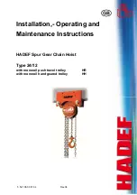
acc. DIN 685-part 5
L11 = pitch increase over 11 chain links
L1 = pitch increase over 1 chain link
Illustration 7
dm= detected link diameter (d1+d2)/2
Illustration 8
Chain dimensions
Table 1
Dimensions
mm
Chain size
3x9 4x12 4,2x12,2 5x15 5,6x15,8 5,6x17 6x18 6,3x19,1
7,1x20,1
L11 105,6 136,6 138,2 170,6 179,1 194,2 203,9 216,4 227,9
L1 9,9 12,7 12,8 15,7 16,6 18 18,9 20 21,2
dm 2,7 3,6 3,8 21,2 5,0 5,0 5,4 5,7 6,4
Table 2
Dimensions
mm
Chain size
7,1x21 7,9x23 8x24 9x24,8 9x27 10x28,1 10x30 13x36 16x45
L11 238,5 260,6 272,1 281,2 300,8 318,6 340,7 408,3 505,6
L1 22,3 24,1 25,3 26,1 28,1 29,6 31,8 37,9 47,4
dm 6,4 7,1 7,2 8,1 8,2 9,0 9,0 11,9 14,4
WARNING!
When the dimensions listed in the table are reached due to wear or deformation, the chain must be
replaced!
12.3
Checking the load hook
Load hook
X = measuring distance hook mouth width
Y = measured length from hook no. 6
H = thickness of hook saddle
Illustration 9
Table 1
Dimension
mm
Capacity
500 kg
1000 kg
1500 kg
2000 kg
3000 kg
5000 kg
10000 kg
20000 kg
X or Y
27/35
33/45
33,5/47
37/52
43,5/62.5
51/79
64/-
82/-
H 16,8 21 25,5 28,3 35,6 43,2 60,4 84,8
Dimensions in the tables are theoretical values without tolerances.
Please fill in the measured
values before putting into
operation:
Capacity kg
X or Y
mm
H mm
CAUTION!
When the dimension of hook opening width is deformed more than 10% or when the dimension of the hook
bottom thickness is fallen short of by 5% due to wear, the hook must be replaced.
12.4
Checking - pawl
A
V
min
kg mm
mm
250 17
16,5
500 14,5
13,5
1000 25
23,5
1500-3000 30 27,5
5000-20000 35 33,5


