HADEF 24/12 Скачать руководство пользователя страница 9


5.52.196.00.01.04  


9


ƒ

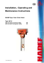
  There are distance tubes (5) and/or washers 

(6) situated on the load bars (2) of the trolley. 

ƒ

  Dimension "X" is set by placing washers (6) 

from the outer to the inner side ("X" increases) 
or from the inner to the outer side ("X" 
decreases). 

ƒ

  Washers (6) and rubber discs (depended on 

type) leave a distance for the load hook. It is 
important that the load hangs in the middle 
under the beam so that the two side plates are 
equally loaded. 

ƒ

  The suspension eye (9) (if existent) for bigger 

load bolts must still be swivelling after it has 
been secured. 

ƒ

  Tighten the hexagon nut (3) and safety nuts (4) 

again. 

ƒ

  Check correct flange width "B" and dimension 

"X". Adjustment must be repeated if necessary.


1 side 

plates 

2 load 

bars 

3 hexagon 

nut 

4 safety 

nuts 

5 distance 

tubes 

6 washers 
7 --- 
8   rubber disc (depended on type) 
9   suspension eye


6.2 

Installation on the beam 

1  Tighten the hexagon nut (3) and safety nuts (4). 
2  Push on the trolley at the face of the beam flange. 
3  If this is not possible, the trolley can also be mounted 

on the beam from below. 

4  Therefore, remove the hexagon nut (3) and the safety 

nut (4) on the side without gear. 

5  Pull apart the side plates (1) as far until it is possible to 

push the trolley onto the beam flange from below. 
Afterwards, push the trolley together to correct gauge. 

6  Secure the washers (6) and distance tubes (5) by 

tightening the hexagon nuts (3) and the safety nuts (4).


Illustration 3 


6.2.1 

Bolt securing with collar 

Securing the load bolts with set collars (1) and safety 
screws (3). 


ƒ

  In order to adjust the beam flange width dismantle 

the safety screws (3) at one trolley side. 

ƒ

  After adjustment of dimension "X" and installation on 

the beam, install the safety screws (3) again and 
secure them with a nut (4). 

ƒ

  When pulling apart the side plates, the trolley drive 

shaft will also be moved. 

ƒ

  To do this, loosen the safety screws at the stern tube 

bearing and secure them again after the side plates 
have been pushed together. 


Illustration 4 


1 set 

collar 

2 load 

bar 

3 safety 

screw 

4 hexagon 

nut 

5 washer


CAUTION!


The distance “X” between the wheel flanges of the trolley wheels must be 
for trolleys up to 3,2 t: 2-3 mm (1-1,5 mm each side) bigger and 
for trolleys from 4 t up: 3-5 mm (1,5-2,5 mm each side) bigger than the flange width "B" of the beam 


Содержание 24/12

Страница 1: ...5 52 196 00 01 04 Rev 04 HADEF Spur Gear Chain Hoist Type 24 12 with monorail push travel trolley HR with monorail hand geared trolley HH Installation Operating and Maintenance Instructions...

Страница 2: ...ges Table of Contents 1 Information 3 2 Safety 4 2 1 Warning notice and symbols 4 2 2 Duty of care of the owner 4 2 3 Requirements for the operating personnel 5 2 4 Appropriate use 5 2 5 Basic safety...

Страница 3: ...any works acc to a certified quality assurance system as per ISO 9001 The production of components at our work is subject to strict intermediate checks After assembly each product is subject to a fina...

Страница 4: ...or they must be suitable for use in area prone to explosion The owner is responsible for this However in everyday operation this degree of safety can only be achieved if all measures required are take...

Страница 5: ...nd load suspension devices must not be used until they have been repaired Only original spare parts must be used Non compliance will result in any warranty claims becoming void Liability and warranty...

Страница 6: ...using may not be in contact somewhere Stop lowering the load when the bottom block or the load is being set down or is prevented from being lowered further The load chain must not be twisted Twisted c...

Страница 7: ...ng temperature fluctuations the correct functionings are endangered by the forming of condensation Ambient temperature 20 C up to 50 C Power operated units 20 up to 40 C Humidity 100 or less but not u...

Страница 8: ...om to 1 N mm 50 146 50 135 66 185 66 185 74 196 74 192 119 215 160 310 Load bar size at beam flange width from to 2 N mm 147 302 136 220 186 310 187 310 197 310 193 310 216 310 Lifting path when reeli...

Страница 9: ...om below 4 Therefore remove the hexagon nut 3 and the safety nut 4 on the side without gear 5 Pull apart the side plates 1 as far until it is possible to push the trolley onto the beam flange from bel...

Страница 10: ...ain fall at the lift side the hand chain wheel turns anti clockwise Illustration5 NOTICE For double lifting mechanism Operate both lifting mechanism synchronous resp evenly CAUTION Run in of chain int...

Страница 11: ...sted by a licensed qualified person before putting in operation An exception is hoists ready for operation acc validated national regulations with EU declaration of conformity Definition qualified per...

Страница 12: ...e effected with utmost care Only qualified persons may do this work Servicing and maintenance work must only be done when the hoist is not loaded Records must be kept of all test results and measures...

Страница 13: ...eck brake function X X Check free wheeling of chain only applicable for ratchet lever hoists with free wheeling mechanism X X Brake check the brake disc thickness X Check sprocket wheels ratchet wheel...

Страница 14: ...nsions listed in the table are reached due to wear or deformation the chain must be replaced 12 3 Checking the load hook Load hook X measuring distance hook mouth width Y measured length from hook no...

Страница 15: ...o that the oil can wet the links affected by wear It is not sufficient to lubricate the chain from the outside as this will not ensure the formation of a lubricating film within the links The adjacent...

Страница 16: ...drive e essure bra ning wear is sition of the l free from fra d chain rranty and or hooks and p e s are worn of essary The ant of class minal load etc l lubricant is each year ake s verified Th ining...

Страница 17: ...eroil 4UH 1 1500 N Load chain Lubricant FM 100 Optimol Viscoleb 1500 Load hook Pulleys Gear rim Drive pinion FM Grease HD2 Mobilgrease FM 222 must be mentioned by order 14 Trouble Please pay attention...

Страница 18: ...housing and got stuck there Release the hook suspend the load again lower the load unload the hoist Hoist does not lower the load Brake too tight Lift the brake Brake too tight due to rust Replace ru...

Отзывы: