90
Plumbing and Connection Options
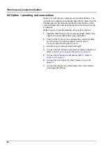
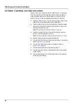
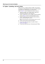
A.10 Option 6 plumbing and connections
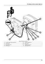
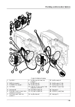
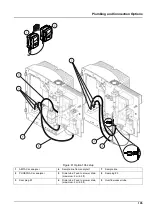
Option 6 uses two sc analyzers with two FILTRAX (FILTRAX 1 and
FILTRAX 2). Samples from both FILTRAX are going into Analyzer 1
using the 2-parameter configuration. The heated drain hose
connects both sc analyzers. The waste from both analyzers is
discharged into a drain through the heated drain hose.
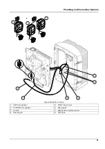
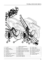
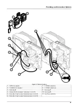
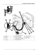
Refer to
and the following instructions for Option 6:
1.
Install both FILTRAX into the sample stream. Refer to the
FILTRAX User Manual for more information.
2.
Install the first sc analyzer (Analyzer 1):
a.
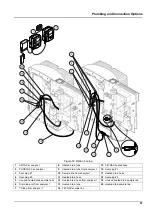
Feed the heated hose from FILTRAX 1 through the
analyzer (
, item 25). Use Seal Plug #1 to secure.
b.
Feed the heated hose from FILTRAX 2 through the
analyzer (item 27). Use Seal Plug #1 to secure.
c.
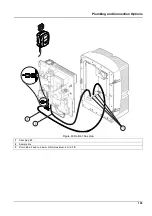
Feed the heated drain hose through the analyzer (item 28).
Use Seal Plug #1 to secure. Connect the heated drain
power connections. Refer to
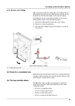
d.
Remove the pre-installed drain tube attached to the valve
block and remove the T-fitting from the drain tube. Retain
for reuse with Analyzer 2.
e.
Connect the heated drain tube to the valve block connector.
f.
Connect the sample line from FILTRAX 1 to the bottom inlet
on Overflow Vessel 1 using the fittings (item 20).
g.
Connect the sample line from FILTRAX 2 to the bottom inlet
on Overflow Vessel 2 using the fittings (item 19).
h.
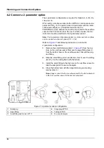
Change the analyzer to the 2-parameter configuration.
Refer to
Connect a 2-parameter option, page 78
i.
Connect Sample Line 1 from the heated drain to Overflow
Vessel 1. Connect Sample Line 2 from the heated drain to
Overflow Vessel 2.
3.
Install the second sc analyzer (Analyzer 2)
a.
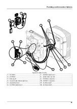
Feed the heated drain hose from Analyzer 1 through
Analyzer 2 (item 13). Use Seal Plug #1 to secure.
b.
Feed the heated drain hose through the analyzer (item 8).
Use Seal Plug #1 to secure. Connect the heated drain
power connections. Refer to
c.
Seal the remaining opening with Seal Plug #3.
d.
Cut 25 mm from the drain tube that was removed from
Analyzer 1. Connect the 25 mm piece of tubing to the
T-fitting on Analyzer 2. Connect the other end of the tubing
to the T-fitting that was removed from Analyzer 1. Refer to
for T-fitting removal.
e.
Connect the drain tube from Analyzer 1 and the drain tube
from Analyzer 2 to the T-fitting.
4.
Connect Sample Line 1 from Analyzer 1 to Overflow Vessel 1
using the fittings (item 16). Connect Sample Line 2 from
Analyzer 1 to Overflow Vessel 2 using the fittings (item 17).
Содержание AMTAX sc
Страница 2: ......
Страница 7: ...7 Specifications Figure 1 Instrument dimensions AMTAX sc...
Страница 12: ...12 General Information...
Страница 18: ...18 Installation Figure 8 Open the enclosure AMTAX indoor sc 1 Latches 3 Lock with key 2 Door hook...
Страница 36: ...36 System Start Up...
Страница 44: ...44 Operation...
Страница 56: ...56 Maintenance...
Страница 64: ...64 Troubleshooting...
Страница 68: ...68 Replacement Parts and Accessorie Exploded view drawings Figure 22 Analyzer enclosure AMTAX sc...
Страница 69: ...69 Replacement Parts and Accessorie Figure 23 Analyzer enclosure AMTAX indoor sc...
Страница 70: ...70 Replacement Parts and Accessorie Figure 24 Analyzer panel overview...
Страница 71: ...71 Replacement Parts and Accessorie Figure 25 Analyzer panel front view details...
Страница 72: ...72 Replacement Parts and Accessorie Figure 26 Analyzer panel back view details...
Страница 76: ...76 Warranty and liability...
Страница 110: ...110 Plumbing and Connection Options...

