background image


5-1 

Chassis views and technical 

specifications 

Chassis views 

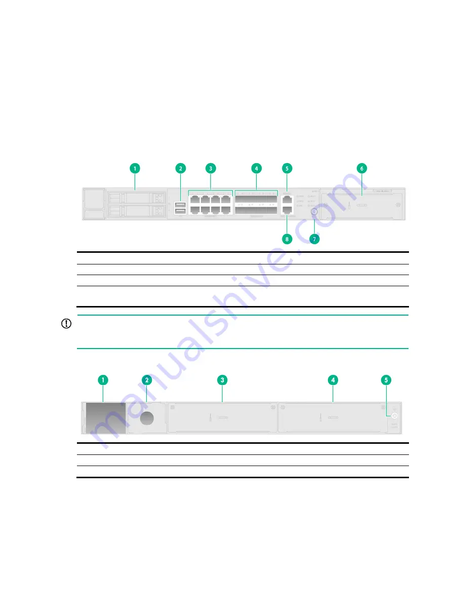
Figure5-1 Front view 


(1) Drive slot 

(2) USB port 

(3) 100/1000BASE-T autosensing Ethernet ports 1 through 7 

(4) 1000BASE-X SFP ports 9 through 16 

(5) Console port 

(6) Expansion slot 

(7) Reset button (RESET) 

(8) 100/1000BASE-T out-of-band 
Ethernet port 


IMPORTANT: 

If you use the console ports numbered 5 and 6 in the figure simultaneously, only the console port 
numbered 6 is activated. 


Figure5-2 Rear view 


(1) Power supply slot PWR1 

(2) Power supply slot PWR2 

(3) Expansion slot 1 

(4) Expansion slot 2 

(5) Grounding screw 


Содержание WX3840X

Страница 1: ...H3C WX3840X Access Controller Installation Guide New H3C Technologies Co Ltd http www h3c com Document version 5W101 20221223 ...

Страница 2: ...respective owners Notice The information in this document is subject to change without notice All contents in this document including statements information and recommendations are believed to be accurate but they are presented without warranty of any kind express or implied H3C shall not be liable for technical or editorial errors or omissions contained herein Environmental protection This produc...

Страница 3: ... replace with actual values Square brackets enclose syntax choices keywords or arguments that are optional x y Braces enclose a set of required syntax choices separated by vertical bars from which you select one x y Square brackets enclose a set of optional syntax choices separated by vertical bars from which you select one or none x y Asterisk marked braces enclose a set of required syntax choice...

Страница 4: ...nts a routing capable device such as a router or Layer 3 switch Represents a generic switch such as a Layer 2 or Layer 3 switch or a router that supports Layer 2 forwarding and other Layer 2 features Represents an access controller a unified wired WLAN module or the access controller engine on a unified wired WLAN switch Represents an access point Represents omnidirectional signals Represents dire...

Страница 5: ...al safety recommendations 1 1 Electrical safety 1 1 Laser safety 1 2 Examining the installation site 1 2 Temperature and humidity 1 2 Cleanliness 1 2 Cooling 1 3 ESD prevention 1 3 EMI 1 4 Lightning protection 1 5 Installation accessories 1 5 Installation tools 1 5 Pre installation checklist 1 6 ...

Страница 6: ...lk areas Keep the chassis clean and dust free Do not place the device near water or in a damp environment Prevent water or moisture from entering the device chassis Ensure good ventilation of the equipment room and keep the air inlet and outlet vents of the device free of obstruction Make sure the operating voltage is in the required range Use a screwdriver to fasten screws After you move the devi...

Страница 7: ...sion Lasting low relative humidity can cause washer contraction and ESD and bring problems including loose captive screws and circuit failure High temperature can accelerate the aging of insulation materials and significantly lower the reliability and lifespan of the device To ensure correct operation of the device the equipment room must meet the temperature and humidity requirements listed in Ta...

Страница 8: ...ESD prevention On the communication network ESD comes from the following sources External electric field such as outdoor high voltage power lines and thunder and lightning Indoor environment floor materials device materials and device components To prevent electrostatic discharge ESD follow these guidelines Ground the device reliably Take dust proof measures for the equipment room For more informa...

Страница 9: ...or clip 2 ESD wrist strap 3 Lock EMI All electromagnetic interference EMI sources from outside or inside of the device and application system adversely affect the device in the following ways A conduction pattern of capacitance coupling Inductance coupling Electromagnetic wave radiation Common impedance including the grounding system coupling To prevent EMI perform the following tasks If AC power ...

Страница 10: ...tect the device from lightning follow these guidelines Make sure the grounding cable of the chassis is grounded reliably Make sure the grounding terminal of the AC power receptacle is grounded reliably Install a lightning protector at the input end of the power supply to enhance the lightning protection capability of the power supply Installation accessories Figure1 3 Installation accessories for ...

Страница 11: ...ing facility The device is far away from radio transmitting stations radar stations and high frequency devices Electromagnetic shielding is used as required Lightning protection The device is reliably grounded The AC power source is reliably grounded Optional Network port lightning protectors are installed Optional A surge protected power strip is installed Electricity safety A UPS is available Th...

Страница 12: ... by using front mounting brackets and slide rails 2 8 Grounding the device 2 9 Optional Installing network port lightning protectors 2 12 Optional Installing a surge protected power strip 2 13 Connecting the device to the network 2 14 Connecting Ethernet cables 2 14 Installing an expansion module 2 15 Installing an expansion module on the front panel 2 15 Installing an expansion module on the rear...

Страница 13: ...f you want to open the chassis contact H3C Support for permission Otherwise H3C shall not be liable for any consequence caused thereby Confirming installation preparations Before you install the device verify that you have read Preparing for installation carefully and the installation site meets all the requirements ...

Страница 14: ... Power on the device Troubleshoot the device Power off the device Operating correctly No Install the device in a 19 inch rack Optional Install network port lightning protectors Optional Install a surge protected power strip Connect the device to the network Installing a power supply Installing an expansion module Installing a drive Connecting the power cord ...

Страница 15: ...r feet to the recessed areas on the chassis bottom 3 Place the device on the workbench with the upside up Make sure the four rubber feet stand firmly on the workbench Figure2 2 Mounting the device on a workbench Installing the device in a 19 inch rack IMPORTANT Keep a minimum distance of 1 U 44 45 mm or 1 75 in between devices in a rack for good heat dissipation Installing the device in a 19 inch ...

Страница 16: ...r mounting brackets 1 Wear the ESD wrist strap and make sure the rack is sturdy and is reliably grounded 2 Use a front mounting bracket to mark the cage nut installation position on the front rack posts Install cage nuts Figure2 5 Installing cage nuts 3 Use the M3 screws supplied with the front mounting brackets to secure the front mounting brackets to both sides of the device Attach the shoulder ...

Страница 17: ...rding to the device installation position in the rack use screws and cage nuts to attach the rear mounting brackets to the rear rack posts Figure2 7 Installing rear mounting brackets 5 Supporting the bottom of the device with one hand and holding the front of the device with the other place the device slowly in the rack Attach the front mounting brackets on the device to ...

Страница 18: ... is an optional component that needs to be separately ordered if needed The rack shelf in this example is for illustration only To install the device by using front mounting brackets and a rack shelf 1 Wear the ESD wrist strap and verify that the rack is sturdy and is reliably grounded 2 Use the M3 screws supplied with the front mounting brackets to attach the front mounting brackets to the device...

Страница 19: ...4 Place the device on the rack shelf and push the device in the rack Attach the front mounting brackets on the device to the front rack posts by using M6 screws and cage nuts as shown in Figure2 10 Figure2 10 Installing the device in the rack ...

Страница 20: ... wrist strap and verify that the rack is sturdy and is reliably grounded 2 Use the screws supplied with the front mounting brackets to attach the front mounting brackets to the device as shown in Figure2 6 3 Attach the slide rails to the rack See Figure2 11 for reference Figure2 11 Installing slide rails 4 Holding both sides of the device push the device in the rack along the slide rails as shown ...

Страница 21: ...e to the grounding system in the equipment room Do not connect it to a fire main or lightning rod To ground the device 1 Use a Phillips screwdriver to remove the grounding screw from the chassis rear panel 2 Use the grounding screw to attach a ring terminal of the grounding cable to the chassis 3 Use one of the following methods to connect the other end of the grounding cable Grounding the device ...

Страница 22: ...vice by using a grounding strip Grounding the device through the rack If the device is installed in a rack you can connect the other end of the grounding cable to the grounding point on the rack Make sure the rack is grounded reliably ...

Страница 23: ...is available at the installation site you can ground the device with a grounding conductor buried in the earth Hammer a 0 5 m 1 64 ft or longer angle iron or steel tube into the earth to serve as a grounding conductor Weld the yellow green grounding cable to the angel iron or steel tube and treat the joint for corrosion protection ...

Страница 24: ...th the device Purchase them yourself as required To install a network port lightning protector for a network port 1 Use a double faced adhesive tape to stick the network port lightning protector onto the device chassis and make sure it is as close to the grounding screw of the device as possible 2 Cut the ground wire of the protector to a length as short as possible as required by the distance bet...

Страница 25: ... strikes IMPORTANT Before installing a surge protected power strip read the instructions in the document that comes with the strip No surge protected power strip is provided with the device Purchase one yourself as required To use a surge protected power strip first connect the AC power line routed from outdoors to the strip and then connect the power cord from the device to the strip You can atta...

Страница 26: ... than 10 cm 3 94 in Keep the fiber end clean Make sure the Tx and Rx ports on a transceiver module are connected to the Rx and Tx ports on the peer end respectively No transceiver modules are provided with the device Purchase transceiver modules yourself as required For more information about the transceiver modules see Optional transceiver modules The fiber ports on the device support only LC con...

Страница 27: ...anel To install an expansion module 1 Wear an ESD wrist strap and make sure it makes good skin contact and is reliably grounded 2 Use a Phillips screwdriver to remove the mounting screw on the filler panel over the expansion module slot Then remove the filler panel Keep the filler panel for future use 3 Rotate out the ejector lever and gently push the expansion module into the slot along the guide...

Страница 28: ...t 1 1 Use a Phillips screwdriver to remove the screws on the filler panel and then remove the filler panel Keep the filler panel for future use 2 Pull the ejector levers on the module outward and slide the module slowly into the slot along the guide rails 3 Press the ejector levers inward until they touch the panel tightly and the module seats into the slot securely 4 Use a Phillips screwdriver to...

Страница 29: ... install a drive 1 Wear an ESD wrist strap and make sure it makes good skin contact and is reliably grounded 2 Remove the filler panel from the drive slot 3 Press the button on the drive panel to release the locking lever 4 Hold the locking lever and push the drive into the slot slowly along the guide rails Then close the locking lever Figure2 20 Installing a drive ...

Страница 30: ...e filler panel for future use 2 Holding the handle of the power supply with one hand and supporting the bottom of the power supply with another hand push the power supply into the slot along the guide rails until the power supply is completely inserted 3 Use a Phillips screwdriver to fasten the captive screws on the power supply Figure2 21 Installing an AC power supply Figure2 22 Installing a DC p...

Страница 31: ...receptacle on the device 2 Use a cable tie to secure the power cord to the handle of the power supply 3 Connect the other end of the AC power cord to the AC power source Figure2 23 Connecting the power cord Connecting a DC power cord 1 Use a flat blade screwdriver to remove the protection cover from the DC power supply 2 Correctly insert the DC plug into the DC power receptacle 3 Use a PH0 flat bl...

Страница 32: ...ctly All the interface cables are cabled indoors If any cable is routed outdoors verify that the network port lightning protectors for network ports and surge protected power strip have been installed Powering on the device 1 Power on the device The device initializes its memory and runs the BootWare The following information appears on the terminal screen System is Starting Press Ctrl D to access...

Страница 33: ... to access the Boot menu To access the Boot menu after the system enters the system image file reading and self compressing process restart the device Loading the main image files Loading file flash system bin Done Loading file flash boot bin Done Image file flash boot bin is self decompressing Done System image is starting Line con0 is available Press ENTER to get started 3 Press Enter at the pro...

Страница 34: ...h Telnet or SSH 1 Configure Telnet login 1 Configure SSH login 1 Log in through the console port 1 About this task 1 Prerequisites 1 Configure terminal parameters 2 Log in to the device 2 Log in from the Web interface 2 About this task 2 Procedure 3 ...

Страница 35: ...lt IP address 192 168 0 100 2 Enter the default username and password as prompted For security purposes change the login password after successful login Configure SSH login 1 Use SSH to access the default IP address 192 168 0 100 2 Enter the default username and password as prompted For security purposes change the login password after successful login Log in through the console port About this ta...

Страница 36: ...arameters as follows Bits per second 9600 Data bits 8 Stop bits 1 Parity None Flow control None Log in to the device Power on the device The following information appears on the terminal screen System is starting Booting Normal Extend BootWare System application is starting Startup configuration file does not exist User interface con0 is available Press ENTER to get started After the device self t...

Страница 37: ... interface through a wired connection 1 Visit the default IP address 192 168 0 100 to access the local Web interface 2 Enter the default username and password and then click the login button For security purposes change the login password as prompted ...

Страница 38: ... Troubleshooting 3 1 Power supply failure 3 1 Symptom 3 1 Solution 3 1 No display or garbled display on the configuration terminal 3 1 Symptom 3 1 Solution 3 1 Software loading failure 3 2 Symptom 3 2 Solution 3 2 ...

Страница 39: ...d display on the configuration terminal Symptom The configuration terminal does not have display or have a garbled display when the device is powered on Solution To resolve the issue 1 Verify that the power system is operation correctly 2 Verify that the console cable is connected correctly to the specified serial port on the configuration terminal 3 Verify that the following settings are configur...

Страница 40: ...yperTerminal to check for errors If an error exists correct the error For example check for the following errors that might occur When you use XMODEM to load software you select a baud rate other than 9600 bps but you have not reset the baud rate for the HyperTerminal When you use TFTP to load software you entered an incorrect IP address software name or TFTP serve path When you use FTP to load so...

Страница 41: ...stics about the device 4 2 Displaying information about the device 4 3 Displaying electrical label information for the device 4 3 Displaying the CPU usage of the device 4 3 Displaying the memory usage of the device 4 4 Displaying the operational status of the built in fans 4 5 Displaying the operating state of power modules 4 5 Rebooting the device 4 5 Restrictions and guidelines 4 6 Configuration...

Страница 42: ... version H3C Comware Software Version 9 1 053 ESS 1054 Copyright c 2004 2022 New H3C Technologies Co Ltd All rights reserved H3C WX3840X uptime is 0 weeks 0 days 0 hours 22 minutes Last reboot reason Power on Boot image flash boot bin Boot image version 9 1 053 ESS 1054 Compiled Jun 21 2022 14 00 00 System image flash system bin System image version 9 1 053 ESS 1054 Compiled Jun 21 2022 14 00 00 w...

Страница 43: ...To view the contents of the default diag file execute the more default diag command in user view and then press the Page Up and Page Down keys Display the operational statistics for each feature module of the device Details not shown H3C display diagnostic information Save or display diagnostic information Y save N display Y N n display clock 03 14 23 UTC Thu 07 14 2022 display version H3C Comware...

Страница 44: ...e An electrical label is a profile of a device It contains the permanent configuration including the serial number manufacturing date MAC address and vendor name Use the display device manuinfo command to display the electrical label information for the device H3C display device manuinfo Slot 1 CPU 0 DEVICE_NAME WX3840X DEVICE_SERIAL_NUMBER 210235A4AU0000001234 MAC_ADDRESS BC22 47FE 40C8 MANUFACTU...

Страница 45: ...usage of the device Use the display memory command to display the memory usage statistics for the device H3C display memory Memory statistics are measured in KB Slot 1 Total Used Free Shared Buffers Cached FreeRatio Mem 16310052 4274260 12035792 0 10072 1248716 73 9 Buffers Cache 3015472 13294580 Swap 0 0 0 Table4 4 Command output Field Description Mem Memory usage information Total Total size of ...

Страница 46: ...wer Power 1 State Absent Power 2 State Normal Table4 6 Command output Field Description Power 1 2 Power module No State Power module state Normal The power module is operating correctly Absent The power module is not in position Fault The power supply has failed Rebooting the device To reboot the device use one of the following methods Reboot the device at the CLI You can remotely reboot the devic...

Страница 47: ... image For more information about the display startup and display boot loader commands see software upgrade commands in the command references The device will not reboot if a file is being accessed Configuration procedure Rebooting the device immediately Task Command Remarks Reboot the device immediately reboot force Available in user view Scheduling a reboot for the device Task Command Remarks Sc...

Страница 48: ...i Contents 5 Chassis views and technical specifications 5 1 Chassis views 5 1 Power supply views 5 2 AC power supply 5 2 DC power supply 5 2 Interface arrangement 5 2 Technical specifications 5 3 ...

Страница 49: ...X SFP ports 9 through 16 5 Console port 6 Expansion slot 7 Reset button RESET 8 100 1000BASE T out of band Ethernet port IMPORTANT If you use the console ports numbered 5 and 6 in the figure simultaneously only the console port numbered 6 is activated Figure5 2 Rear view 1 Power supply slot PWR1 2 Power supply slot PWR2 3 Expansion slot 1 4 Expansion slot 2 5 Grounding screw ...

Страница 50: ...gabitEthernet 1 0 1 through GigabitEthernet 1 0 16 You can identify an interface by its mark GigabitEthernet 1 0 1 through GigabitEthernet 1 0 8 100 1000BASE T autosensing Ethernet ports GigabitEthernet 1 0 9 through GigabitEthernet 1 0 16 1000BASE X SFP ports Internal interfaces GigabitEthernet1 0 17 and GigabitEthernet1 0 18 are 100 1000BASE T autosensing Ethernet interfaces for connecting expan...

Страница 51: ...ions H W D excluding the rubber feet and mounting brackets 44 440 435 mm 1 73 17 32 17 13 in AC power supply Rated voltage range 100 to 240 VAC 50 60 Hz DC power supply Rated voltage range 48 VDC to 60 VDC System power consumption 36 W to 107 W Weight 9 kg 19 84 lb Operating temperature 0 C to 45 C 32 F to 113 F Operating humidity non condensing 5 RH to 95 RH Table5 2 AC power supply specification...

Страница 52: ...i Contents 6 LEDs 6 1 LEDs 6 1 LED description 6 1 ...

Страница 53: ... Mark Status Description Power module LED PWR1 PWR2 Steady green The power module is operating correctly Steady red An exception has occurred on the power module Off No power module is present System status LED SYS Slow flashing green once every 2 seconds The device is operating correctly Fast flashing green four times per second The device is starting up Steady red The device has failed self POST...

Страница 54: ... present Flashing green The port is receiving and sending data Off No link is present 100 1000BASE T autosensing Ethernet port LED N A Steady yellow A 100 Mbps link is present Flashing yellow The port is receiving and sending data at 100 Mbps Steady green A 1000 Mbps link is present Flashing green The port is receiving and sending data at 1000 Mbps Off No link is present 1000BASE X SFP port LED N ...

Страница 55: ...1 Contents 7 Optional transceiver modules 7 1 Views 7 1 Specifications 7 1 ...

Страница 56: ...nsceiver module that has MM in its name supports multi mode optical fibers A transceiver module that has SM in its name supports single mode optical fibers The H3C transceiver modules are subject to change over time For the most recent list of H3C transceiver modules contact Technical Support or marketing staff Table7 1 SFP GE SX MM850 A transceiver module specifications Item SFP GE SX MM850 A Cen...

Страница 57: ...tivity 17 dBm Light saturation 3 dBm Table7 2 SFP GE LX SM1310 A specifications Item SFP GE LX SM1310 A Central wavelength 1310 nm Max transmission distance 10 km 6 21 miles Data rate 1250 Mb s Connector type Duplex LC connector Fiber mode SMF Fiber diameter 9 μm Output power 9 5 to 3 dBm Receiver sensitivity 20 dBm Light saturation 3 dBm ...

Отзывы: