background image


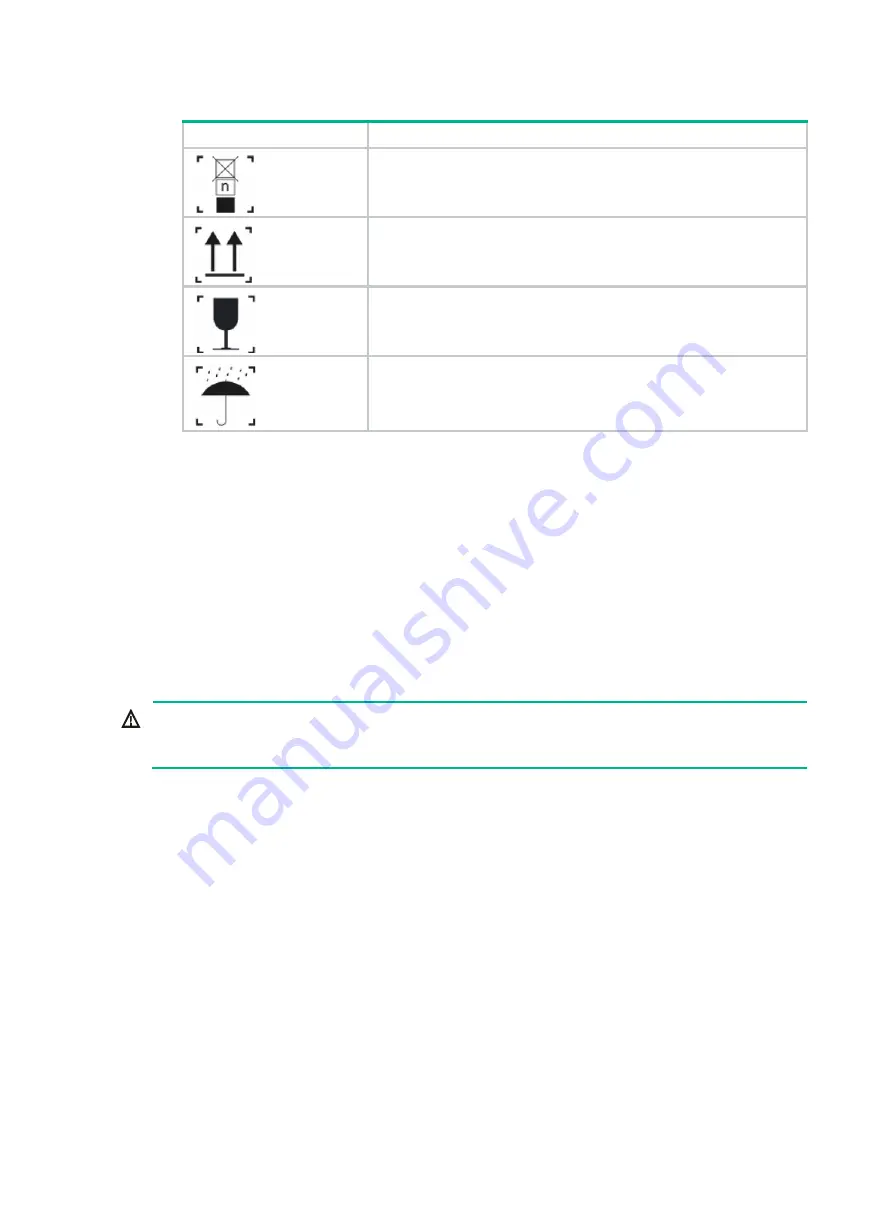
Figure1-1 Packing symbols 

Symbol 

Description 


The devices shall not be vertically stacked beyond the specified 
number. 


Place the device with the arrows up. 


The device is fragile. Handle it with care. 


Keep the device from humidity, rains, and wet floor. 


Electrical safety 


Carefully examine your work area for possible hazards such as moist floors, ungrounded power 
extension cables, and missing safety grounds. 


Locate the emergency power-off switch in the room before installation. Shut the power off at 
once in case accident occurs. 


Do not work alone when the firewall has power. 


Always verify that the power has been disconnected. 

Laser safety 


WARNING! 

Disconnected optical fibers or transceiver modules might emit invisible laser light. Do not stare into 
beams or view directly with optical instruments when the firewall is operating. 


The firewall is a Class 1 laser device. 


Before you disconnect the fiber connector, execute the 

shutdown

 command in interface view 

to disable the optical source. 


Install dust caps to disconnected optical fiber connectors and ports on disconnected transceiver 
modules to avoid damage caused by built-up dust. 


Insert a dust plug into empty fiber ports. 

Handling safety 

When you move the firewall, follow these guidelines: 


Move and unpack the firewall carefully to avoid firewall damage. 


Unpack the firewall at least half an hour and power on the firewall at least two hours after you 
move it from a place below 0°C (32°F) to the equipment room. This prevents condensation and 
even damage to the firewall. 


Use a safety hand truck when you move multiple firewalls. 

Содержание SecPath F100-X-G3

Страница 1: ...H3C SecPath F100 X G3 F1000 X G3 Firewalls Installation Guide New H3C Technologies Co Ltd http www h3c com Document version 6W101 20201218...

Страница 2: ...espective owners Notice The information in this document is subject to change without notice All contents in this document including statements information and recommendations are believed to be accur...

Страница 3: ...nclose syntax choices keywords or arguments that are optional x y Braces enclose a set of required syntax choices separated by vertical bars from which you select one x y Square brackets enclose a set...

Страница 4: ...s a Layer 2 or Layer 3 switch or a router that supports Layer 2 forwarding and other Layer 2 features Represents an access controller a unified wired WLAN module or the access controller engine on a u...

Страница 5: ...Documentation feedback You can e mail your comments about product documentation to info h3c com We appreciate your comments...

Страница 6: ...hernet cables 17 Connecting a copper Ethernet port 17 Connecting a fiber port 18 Connecting power cords 19 Connecting an AC power cord 20 Connecting a DC power cord 21 Connecting a high voltage DC pow...

Страница 7: ...tus of power supplies 5 34 Displaying the temperature information of the firewall 5 34 Displaying the operational statistics of the firewall 5 35 Displaying transceiver module information 5 35 Rebooti...

Страница 8: ...t if not understood or followed can result in data loss data corruption or damage to hardware or software General safety recommendations Do not place the firewall on an unstable case or desk The firew...

Страница 9: ...odules might emit invisible laser light Do not stare into beams or view directly with optical instruments when the firewall is operating The firewall is a Class 1 laser device Before you disconnect th...

Страница 10: ...sions and weights Temperature and humidity Make sure the temperature and humidity in the equipment room meet the requirements described in Table1 1 Lasting high relative humidity can cause poor insula...

Страница 11: ...n for the airflow direction of the firewall to match the ventilation designs at the installation site Reserve a minimum clearance of 100 mm 3 94 in around the chassis inlet and outlet air vents Mainta...

Страница 12: ...around your wrist to keep good contact with the skin 3 Secure the wrist strap lock and the alligator clip lock together 4 Attach the alligator clip to the rack or the workbench Figure1 3 Attaching an...

Страница 13: ...receptacle on the device If a network cable is routed from outdoors for connecting to an Ethernet port on the firewall connect the network cable first to a network port lightning arrester before conne...

Страница 14: ...is a minimum clearance of 100 mm 3 94 in around the inlet and outlet air vents for heat dissipation of the firewall chassis A good ventilation system is available at the installation site Temperature...

Страница 15: ...bly grounded The grounding terminal of the AC power receptacle is reliably grounded Optional A power lightning arrester is installed Electricity safety Equip a UPS Locate the power switch in the equip...

Страница 16: ...able for any consequence The firewall can be installed on a workbench or in a 19 inch rack Figure2 1 Firewall installation flow NOTE End Determine the installation position Mount the firewall on a wor...

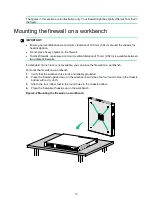
Страница 17: ...um vertical distance of 15 mm 0 59 in is available between two adjacent firewalls If a standard 19 inch rack is not available you can place the firewall on a workbench To mount the firewall on a workb...

Страница 18: ...install the firewall in a standard 19 inch rack 1 Wear an ESD wrist strap and make sure the wrist strap makes good skin contact and is reliably grounded 2 Unpack the firewall and accessories 3 Mark t...

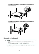
Страница 19: ...in attach the rear mounting brackets to the rear rack posts with the wide flange outside the rack To prevent the rear mounting brackets from obstructing closing of the rack door ensure a distance gre...

Страница 20: ...he rear mounting brackets outside the rack Grounding the firewall WARNING Correctly connecting the firewall grounding cable is crucial to lightning protection and EMI protection Do not connect the fir...

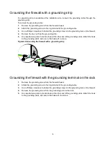
Страница 21: ...to bend a hook at the other end of the grounding cable Attach the hook to the grounding point and secure the hook with a screw Figure2 9 Grounding the firewall with a grounding strip Grounding the fir...

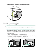
Страница 22: ...le power supplies For the power supplies available for the firewalls see Appendix A Chassis views and technical specifications To install a power supply 1 Remove the filler panel if any from the targe...

Страница 23: ...down the ejector levers of the interface module while inserting it into an upper slot No interface modules are provided with the firewall Purchase them as needed For the interface modules available f...

Страница 24: ...with any drives and cannot recognize drives from other vendors Purchase drives from H3C as needed To install a drive 1 Wear an ESD wrist strap and make sure it makes good skin contact and is reliably...

Страница 25: ...nd clean Make sure the fiber connector matches the transceiver module Before connecting a fiber make sure the optical power at the receiving end does not exceed the transceiver module s upper threshol...

Страница 26: ...iber connector 4 Identify the Rx and Tx ports on the transceiver module Plug one end of the optical fiber into the transceiver module in the firewall and plug the other end into the transceiver module...

Страница 27: ...rd to an AC power source Figure2 19 Connecting an AC power cord using a power cord retainer clip to secure the power cord Figure2 20 Connecting an AC power cord using a cable tie to secure the power c...

Страница 28: ...receptacle on the power supply The power cord connector and power receptacle form a disorientation rejection structure If you cannot insert the connector into the receptacle re orient the connector ra...

Страница 29: ...tage DC power cord see Connecting an AC power cord for an F1000 C G3 F1000 S G3 F1000 A G3 or F1000 E G3 firewall Verifying the installation Verify the following items to ensure correct installation T...

Страница 30: ...the serial console port or micro USB console port you must run a terminal emulator program TeraTermPro or PuTTY on your configuration terminal and configure the following settings for the terminal Fo...

Страница 31: ...ting Normal Extended BootWare The Extended BootWare is self decompressing Done H3C BootWare Version 2 00 Compiled Date Sep 10 2019 CPU Type xxx CPU Clock Speed 1000MHz Memory Type DDR3 SDRAM Memory Si...

Страница 32: ...own Answer tests in the engine Known answer test for SHA1 passed Known answer test for HMAC SHA1 passed Known answer test for AES passed Known answer test for RSA signature verification passed Known a...

Страница 33: ...to a management Ethernet port on the firewall for example 0 MGMT 2 Configure an IP address in subnet 192 168 0 0 24 for the PC Make sure the PC and the firewall are reachable to each other The PC must...

Страница 34: ...3 27 4 Specify an IP address for the network port of the PC Make sure the device and PC are reachable to each other 5 Run the Telnet client on the PC and enter the default login information...

Страница 35: ...ng procedure replaces an AC power supply To replace an AC power supply 1 Face the rear panel of the firewall 2 Remove the cable tie from the power cord and then remove the power cord from the power su...

Страница 36: ...rt way out of the slot along the slide rails Supporting the bottom of the interface module with one hand gently pull the interface module out of the slot with the other 4 Put the removed interface mod...

Страница 37: ...ating To replace a transceiver module 1 Use the shutdown command in interface view at the CLI to shut down the optical source before you remove the fiber connector 2 Remove the LC connectors with the...

Страница 38: ...Ver A2 CPLD_A 2 0 CPLD_B 2 0 CPLD_C 65535 0 CFCard Num 0 Displaying the software and hardware version information for the firewall Use the display version command to display software and hardware vers...

Страница 39: ...H3C Fan 0 The operation is not supported on the specified fan Fan 1 The operation is not supported on the specified fan Fan 2 The operation is not supported on the specified fan Power 0 The operation...

Страница 40: ...l Used Free Shared Buffers Cached FreeRatio Mem 1718140 921604 796536 0 1108 187644 46 4 Buffers Cache 732852 985288 Swap 0 0 0 Table5 3 Output description Field Description Slot Slot number of the in...

Страница 41: ...lay environment System Temperature information degree centigrade Sensor Temperature LowerLimit Warning UpperLimit Alarm UpperLimit Shutdown U pperLimit inflow 1 26 5 48 56 NA NOTE Only the F100 A G3 F...

Страница 42: ...diag gz file a Execute the gunzip diag gz command in user view to decompress the file b Execute the more diag command c Press Pg Up and Pg Down Display the operational statistics for each functional...

Страница 43: ...n the firewall is to be rebooted the system does not execute the reboot command for security To reboot a firewall use one of the following methods Use the reboot command to reboot the firewall immedia...

Страница 44: ...ssue 1 Verify that the power supply system is operating correctly 2 Verify that the serial console cable or micro USB console cable is correctly connected 3 Verify that the serial console cable or mic...

Страница 45: ...the firewall temperature in the display environment command output varies by firewall model NOTE Only the F100 A G3 F100 E G3 F1000 C G3 F1000 S G3 F1000 A G3 and F1000 E G3 firewalls support the disp...

Страница 46: ...Network data encryption modules 8 Power supplies 8 AC power supply 9 DC power supply 9 High voltage DC power supply 10 Dimensions and weights 11 Chassis 11 Interface modules 11 Network data encryption...

Страница 47: ...ass ports Two USB ports One console port One drive slot Figure1 1 Front panel 1 Drive slot 2 Console port CONSOLE 3 USB ports 4 Combo interfaces 5 Bypass ports 6 10 100 1000BASE T copper ports 7 LEDs...

Страница 48: ...ace module slot 1 3 Interface module slot 2 not supported 4 Grounding screw F100 E G3 The F100 E G3 firewall provides the following ports and slots on the front panel Sixteen 10 100 1000BASE T autosen...

Страница 49: ...ng copper ports including two management Ethernet ports Twelve 1000BASE X fiber ports Four 10GBASE R fiber ports Two USB ports One console port One micro USB port Two drive slots Figure1 7 Front panel...

Страница 50: ...000BASE T autosensing copper ports including two management Ethernet ports Twelve 1000BASE X fiber ports Four 10GBASE R fiber ports Two USB ports One console port One micro USB port Two drive slots Fi...

Страница 51: ...teen 10 100 1000BASE T autosensing copper ports including two management Ethernet ports Eight 1000BASE X fiber ports Eight 10GBASE R fiber ports Two USB ports One console port One micro USB port Two d...

Страница 52: ...supported Slot 1 Slots 1 and 2 Slot 2 Slots 2 and 4 NS NIM TG4A3 Not supported Slot 1 Slots 1 and 2 Slot 2 Slots 2 and 4 NS NIM TG6A Not supported Not supported Not supported Slot 1 Slots 1 and 3 NSQM...

Страница 53: ...ure1 14 Front panel of the NSQM1GP4FBA interface module 1 1000BASE X fiber ports 2 Captive screw 3 Ejector lever NS NIM TG4A3 The NS NIM TG4A3 interface module provides four 10GBASE R fiber ports Figu...

Страница 54: ...able software versions NSQM1F1KGM0 F100 A G3 F100 E G3 Slot 1 R9323 and later F1000 C G3 E8601P07 and later F1000 S G3 F1000 A G3 F1000 E G3 Slots 1 to 3 E8601P07 and later NSQM1F1KGMB F100 A G3 F100...

Страница 55: ...lable power supplies F100 C G3 F100 M G3 F100 S G3 One built in power supply F100 A G3 F100 E G3 Two built in power supplies F1000 C G3 F1000 S G3 F1000 A G3 F1000 E G3 Two power supply slots supporti...

Страница 56: ...pply CAUTION You can install high voltage DC power supplies only on F1000 C G3 F1000 S G3 F1000 A G3 and F1000 E G3 firewalls PSR450 12AHD The PSR450 12AHD power supply provides a maximum output power...

Страница 57: ...22 05 lb Interface modules Table1 5 Interface module dimensions and weights Interface module model Dimensions H W D Weight NSQM1GT4PFC 19 150 172 9 mm 0 75 5 91 6 81 in 0 45 kg 0 99 lb NSQM1TG4FBA 19...

Страница 58: ...Table1 8 Chassis power consumption Firewall model Power consumption F100 C G3 F100 M G3 F100 S G3 30 W F100 A G3 F100 E G3 79 W F1000 C G3 F1000 S G3 F1000 A G3 F1000 E G3 180 W Interface modules Tabl...

Страница 59: ...supply specifications Model Rated input voltage range Maximum input current Maximum power PSR450 12AHD AC input 100 VAC to 240 VAC 50 Hz or 60 Hz 7 A 450 W High voltage DC input 240 VAC to 380 VAC 3 5...

Страница 60: ...RJ 45 Standard compliance 802 3 802 3u and 802 3ab Interface type MDI MDI X autosensing Cable type Category 5 or higher twisted pair cable Transmission distance 100 m 328 08 ft Interface speed and dup...

Страница 61: ...e optical fiber 80 km 49 71 miles SFP GE LH100 SM1550 1550 nm LC 9 125 m single mode optical fiber 100 km 62 14 miles 10 GE fiber port The F1000 C G3 and F1000 E G3 firewalls each provide four 10GBASE...

Страница 62: ...M131 0 1310 nm LC 62 5 125 m multi mode optical fiber 220 m 721 78 ft 50 125 m multi mode optical fiber 220 m 721 78 ft 100 m 328 08 ft SFP XG LX SM1310 1310 nm LC 9 125 m single mode optical fiber 10...

Страница 63: ...i Contents 1 Appendix B LEDs 1...

Страница 64: ...port is receiving and sending data at 1000 Mbps 10GBASE R Off No link is present on the port Steady green A 10 Gbps link is present on the port Flashing green The port is receiving and sending data at...

Страница 65: ...1 Appendix C Cables 1 1 Console cable 1 1 RJ 45 to DB9 console cable 1 1 Micro USB console cable 1 1 Ethernet twisted pair cable 1 2 Introduction 1 2 Making an Ethernet twisted pair cable 1 5 Optical...

Страница 66: ...on the firewall Figure1 1 RJ 45 to DB9 console cable Table1 1 RJ 45 to DB9 console cable pinouts RJ 45 Signal Direction DB 9 1 RTS 7 2 DTR 4 3 TXD 3 4 CD 1 5 GND 5 6 RXD 2 7 DSR 6 8 CTS 8 Micro USB c...

Страница 67: ...twisted pair cables can be classified into category 3 category 4 category 5 category 5e category 6 and category 7 cables based on performance In LANs category 5 category 5e and category 6 are commonly...

Страница 68: ...pin 3 white green stripe pin 4 blue solid pin 5 white blue stripe pin 6 green solid pin 7 white brown stripe pin 8 brown solid Ethernet twisted pair cables can be classified into straight through and...

Страница 69: ...directional data cable C 5 Reserved N A BIDC Bi directional data cable C 6 Rx Receives data BIDB Bi directional data cable B 7 Reserved N A BIDD Bi directional data cable D 8 Reserved N A BIDD Bi dire...

Страница 70: ...air cable 1 Cut the cable to a required length with the crimping tool 2 Strip off an appropriate length of the cable sheath The length is typically that of the RJ 45 connector 3 Untwist the pairs so t...

Страница 71: ...6 shows an LC connector Figure1 6 LC connector Follow these guidelines when you connect an optical fiber Before connecting an optical fiber make sure the connector and cable type match the interface m...

Отзывы: