18
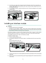
To connect a copper Ethernet port:
1.
Connect one end of the Ethernet cable to the copper Ethernet port of the firewall, and the other
end to the Ethernet port of the peer device.
2.
Examine whether the LEDs of the Ethernet port are normal. For more information about LEDs,
see "Appendix B LEDs."
After connecting the firewall to the network, you can use the
ping
or
tracert
command to
examine network connectivity. For more information, see the related command reference.
Connecting a fiber port
WARNING!
Disconnected optical fibers or transceiver modules might emit invisible laser light. Do not stare into
beams or view directly with optical instruments when the firewall is operating.
CAUTION:
•
Never bend or curve a fiber excessively. The bend radius of a fiber must be not less than 100 mm
(3.94 in).
•
Keep the fiber end clean.
•
Make sure the fiber connector matches the transceiver module.
•
Before connecting a fiber, make sure the optical power at the receiving end does not exceed the
transceiver module's upper threshold of the optical receive power. If the optical power at the
receiving end exceeds the threshold, the transceiver module might be damaged.
•
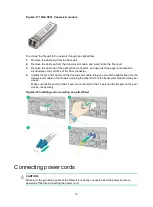
Do not install a transceiver module connected with a fiber into a fiber port. To connect an optical
fiber, first install the transceiver module in the fiber port and then connect the fiber.
•
Insert a dust plug into any open fiber port.
•
Make sure the Tx and Rx ports on a transceiver module are connected to the Rx and Tx ports on
the peer end, respectively.
The firewall supports GE SFP transceiver modules and 10GE SFP+ transceiver modules. For the
transceiver module specifications, see "GE fiber Ethernet port" and "10 GE fiber Ethernet port."
No transceiver module is provided with the firewall. As a best practice, use H3C transceiver
modules.
Figure2-16 GE SFP transceiver module
Содержание SecPath F100-X-G3
Страница 63: ...i Contents 1 Appendix B LEDs 1...


