7
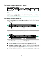
Table 5 Distance requirements between the front and rear rack posts
Switch
model
Installation method
Min. distance
between the front
and rear rack posts
Max. distance
between the front
and rear rack posts
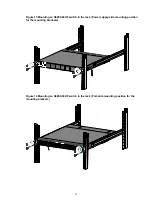
S6890-54HF
S6890-30HF
S6890-44HF
Using the mounting brackets and
long slide rails (provided)
621 mm (24.45 in)
854 mm (33.62 in)
Using the mounting brackets and
short slide rails (optional)
401 mm (15.79 in)
634 mm (24.96 in)
Table 6 Distance requirements between the front rack posts and the front and rear doors
Mounting bracket
position
Min. distance between the front
rack ports and the front door
Min. distance between the front
rack posts and the rear door
Port side
130 mm (5.12 in)
540 mm (21.26 in)
Power supply side
80 mm (3.15 in)
590 mm (23.23 in)
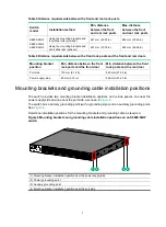
Mounting brackets and grounding cable installation positions
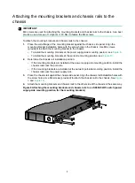
The switch provides two mounting bracket installation positions on the side panels: one near the
power supply side and one near the port side, as shown in
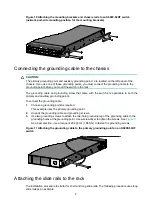
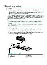
The switch has a primary grounding point (with a grounding sign) and an auxiliary grounding point.
See
Determine installation positions for the mounting brackets and grounding cable as required.
Figure 8 Mounting brackets and grounding cable installation positions on an S6890-54HF
switch
(1) Mounting bracket installation position near the power supply side
(2) Primary grounding point
(3) Auxiliary grounding point
(4) Mounting bracket installation position near the port side
1
2
3
4


