background image


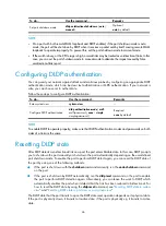
44 

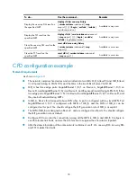
To do… 

Use the command… 

Remarks 

Enable DLDP globally  

dldp enable 

Required 
Globally disabled by default 

Enter Ethernet 

port view 

interface

 interface-type 

interface-number


Enter Ethernet 

port view or port 
group view  

Enter port group 
view 

port-group manual 

port-group-name


Either of the two is required. 
Configurations made in Ethernet port 

view apply to the current port only; 
configurations made in port group view 

apply to all ports in the port group.  

Enable DLDP 

dldp enable 

Required 
Disabled on a port by default 


NOTE: 


DLDP takes effect only on Ethernet interfaces (optical or copper). 


DLDP can detect unidirectional links only after all physical links are connected. Therefore, before 
enabling DLDP, make sure that optical fibers or copper twisted pairs are connected. 


Setting DLDP mode 

DLDP works in normal or enhanced mode:  


In normal mode, DLDP does not actively detect neighbors when the corresponding neighbor entries 
age out. The system can identify only one type of unidirectional links: cross-connected fibers.  


In enhanced mode, DLDP actively detects neighbors when the corresponding neighbor entries age 
out,  so  the  system  can  identify  two  types  of  unidirectional links: cross-connected fibers and 

disconnected fibers. 

Follow these steps to set DLDP mode: 

To do… 

Use the command… 

Remarks 

Enter system view 

system-view 

— 

Set DLDP mode  

dldp work-mode 

{

 enhance

 | 

normal 

}


Optional 
Normal by default 


Setting the interval for sending advertisement 

packets 

DLDP detects unidirectional links by sending Advertisement packets. To ensure that DLDP can detect 

unidirectional links in time without affecting network performance, set the advertisement interval 
appropriately depending on your network environment. The interval should be set shorter than one third 

of the STP convergence time. If the interval is too long, STP loops may occur before unidirectional links 

are detected and shut down. If the interval is too short, the number of advertisement packets will increase. 

H3C recommends you use the default interval in most cases.  
Follow these steps to set the interval to send Advertisement packets: 

Содержание s5800 series

Страница 1: ...H3C S5820X S5800 Switch Series High Availability Configuration Guide Hangzhou H3C Technologies Co Ltd http www h3c com Software version Release 1211 Document version 6W100 20110415 ...

Страница 2: ...are Secware Storware NQA VVG V2 G Vn G PSPT XGbus N Bus TiGem InnoVision and HUASAN are trademarks of Hangzhou H3C Technologies Co Ltd All other trademarks that may be mentioned in this manual are the property of their respective owners Notice The information in this document is subject to change without notice Every effort has been made in the preparation of this document to ensure accuracy of th...

Страница 3: ... network recovery This preface includes Audience Added and modified features Conventions About the H3C S5800 S5820X documentation set Obtaining documentation Technical support Documentation feedback Audience This documentation is intended for Network planners Field technical support and servicing engineers Network administrators working with the S5800 and S5820X series Added and modified features ...

Страница 4: ...scription Boldface Bold text represents commands and keywords that you enter literally as shown Italic Italic text represents arguments that you replace with actual values Square brackets enclose syntax choices keywords or arguments that are optional x y Braces enclose a set of required syntax choices separated by vertical bars from which you select one x y Square brackets enclose a set of optiona...

Страница 5: ...ble device such as a router or Layer 3 switch Represents a generic switch such as a Layer 2 or Layer 3 switch or a router that supports Layer 2 forwarding and other Layer 2 features About the H3C S5800 S5820X documentation set The H3C S5800 S5820X documentation set includes Category Documents Purposes Marketing brochures Describe product specifications and benefits Product description and specific...

Страница 6: ...ns of the pluggable modules available for the products S5800 60C PWR Ethernet Switch Hot Swappable Power Module Ordering Guide Guides you through ordering the hot swappable power modules available for the S5800 60C PWR switches in different cases Power configuration RPS Ordering Information for H3C Low End Ethernet Switches Provides the RPS and switch compatibility matrix and RPS cable specificati...

Страница 7: ...e including the version history hardware and software compatibility matrix version upgrade information technical support information and software upgrading Obtaining documentation You can access the most up to date H3C product documentation on the World Wide Web at http www h3c com Click the links on the top navigation bar to obtain different categories of product documentation Technical Support D...

Страница 8: ... detection 11 Configuring errored frame seconds event detection 12 Configuring OAM remote loopback 12 Enabling Ethernet OAM remote loopback 12 Rejecting the Ethernet OAM remote loopback request from a remote port 13 Displaying and maintaining Ethernet OAM configuration 14 Ethernet OAM configuration example 14 CFD configuration 17 Overview 17 Basic concepts in CFD 17 CFD functions 19 Protocols and ...

Страница 9: ...6 RRPPDUs 58 RRPP timers 59 How RRPP works 59 Typical RRPP networking 61 Protocols and standards 64 RRPP configuration task list 64 Creating an RRPP domain 65 Configuring control VLANs 65 Configuring protected VLANs 66 Configuring RRPP rings 66 Configuring RRPP ports 67 Configuring RRPP nodes 67 Activating an RRPP domain 69 Configuring RRPP timers 69 Configuring RRPP fast detection 70 Enabling fas...

Страница 10: ... group member ports 110 Displaying and maintaining Monitor Link 111 Monitor Link configuration example 111 VRRP configuration 115 VRRP overview 115 VRRP standard protocol mode 116 Introduction to VRRP group 116 VRRP timers 118 Packet format 118 Principles of VRRP 120 VRRP tracking 120 VRRP application 121 VRRP load balancing mode 122 Overview 122 Assigning virtual MAC addresses 123 Virtual forward...

Страница 11: ...guring the backup VLAN 180 Displaying and maintaining stateful failover 180 Stateful failover configuration example 180 Configuration guidelines 182 BFD configuration 183 Introduction to BFD 183 How BFD works 183 BFD packet format 185 Supported features 187 Protocols and standards 187 Configuring BFD basic functions 188 Configuration prerequisites 188 Configuration procedure 188 Enabling trap 189 ...

Страница 12: ...RP master to monitor the uplinks 205 Static routing track NQA collaboration configuration example 209 Static routing track BFD collaboration configuration example 213 VRRP track interface management collaboration configuration example the master monitors the uplink interface 217 Index 220 ...

Страница 13: ... from being affected by failures Device and link redundancy and switchover 3 Enable the system to recover as fast as possible Fault detection diagnosis isolation and recovery technologies The level 1 availability requirement should be considered during the design and production process of network devices The level 2 availability requirement should be considered during network design The level 3 av...

Страница 14: ...inistration and Maintenance OAM mechanism used for link connectivity detection fault verification and fault location CFD configuration in the High Availability Configuration Guide DLDP The Device link detection protocol DLDP deals with unidirectional links that may occur in a network On detecting a unidirectional link DLDP as configured can shut down the related port automatically or prompt users ...

Страница 15: ... to ensure continuity of network services For more information about protection switchover technologies see Table 3 Table 3 Protection switchover technologies Technology Introduction Reference Ethernet Link Aggregation Ethernet link aggregation most often simply called link aggregation aggregates multiple physical Ethernet links into one logical link to increase link bandwidth beyond the limits of...

Страница 16: ...ithout requiring the cooperation of other devices IS IS supports this feature IS IS configuration in the Layer 3 IP Routing Configuration Guide Stateful Failover Two devices back up the services of each other to ensure that the services on them are consistent If one device fails the other device can take over the services by using VRRP or dynamic routing protocols Because the other device has alre...

Страница 17: ...s As a tool monitoring Layer 2 link status Ethernet OAM mainly addresses common link related issues on the last mile When you enable Ethernet OAM on two devices connected by a point to point link you can monitor the status of the link Major functions of Ethernet OAM Ethernet OAM is an effective tool for management and maintenance of Ethernet networks helping to ensure network stability It includes...

Страница 18: ...gs Status information of an Ethernet OAM entity Code Type of the Ethernet OAMPDU NOTE Throughout this document a port with Ethernet OAM enabled is an Ethernet OAM entity or an OAM entity Table 5 Functions of different types of OAMPDUs OAMPDU type Function Information OAMPDU Used for transmitting state information of an Ethernet OAM entity including the information about the local device and remote...

Страница 19: ...le Available Transmitting Information OAMPDUs Available Available Transmitting Event Notification OAMPDUs Available Available Transmitting Information OAMPDUs without any TLV Available Available Transmitting Loopback Control OAMPDUs Available Unavailable Responding to Loopback Control OAMPDUs Available if both sides operate in active OAM mode Available NOTE OAM connections can be initiated only by...

Страница 20: ...ystem transforms the period of detecting errored frame period events into the maximum number of 64 byte frames that a port can send in the specific period The system takes the maximum number of frames sent as the period The maximum number of frames sent is calculated using this formula the maximum number of frames interface bandwidth bps errored frame period event detection period in ms 64 8 1000 ...

Страница 21: ... check the link status and locate link failures Performing remote loopback periodically helps to detect network faults in time Furthermore performing remote loopback by network segments helps to locate network faults Protocols and Standards IEEE 802 3h Carrier Sense Multiple Access with Collision Detection CSMA CD Access Method and Physical Layer Specifications Ethernet OAM configuration task list...

Страница 22: ...k whether the Ethernet OAM connection is normal If an Ethernet OAM entity receives no Information OAMPDU within the Ethernet OAM connection timeout time the Ethernet OAM connection is considered disconnected By adjusting the handshake packet transmission interval and the connection timeout timer you can change the detection time resolution for Ethernet OAM connections Follow these steps to configu...

Страница 23: ...d frame event detection An errored frame event occurs when the number of detected error frames over a specific interval exceeds the configured threshold Follow these steps to configure errored frame event detection To do Use the command Remarks Enter system view system view Configure the errored frame event detection interval oam errored frame period period value Optional 1 second by default Confi...

Страница 24: ...e seconds detection interval Otherwise no errored frame seconds event can be generated Configuring OAM remote loopback Enabling Ethernet OAM remote loopback When you enable Ethernet OAM remote loopback on a port the port sends Loopback Control OAMPDUs to a remote port and the remote port enters the loopback state The port then sends test frames to the remote port By observing how many of these tes...

Страница 25: ...ll shut down and then come up Ethernet OAM remote loopback is disabled when you execute the undo oam enable command to disable Ethernet OAM when you execute the undo oam loopback interface or undo oam loopback command to disable Ethernet OAM remote loopback or when the Ethernet OAM connection times out Ethernet OAM remote loopback is only applicable to individual links It is not applicable to link...

Страница 26: ...link error events after an Ethernet OAM connection is established display oam link event local remote interface interface type interface number begin exclude include regular expression Display the information about an Ethernet OAM connection display oam local remote interface interface type interface number begin exclude include regular expression Available in any view Clear statistics on Ethernet...

Страница 27: ...Verify the configuration Use the display oam configuration command to display the Ethernet OAM configuration For example Display the Ethernet OAM configuration on Switch A SwitchA display oam configuration Configuration of the link event window threshold Errored symbol Event period in seconds 1 Errored symbol Event threshold 1 Errored frame Event period in seconds 20 Errored frame Event threshold ...

Страница 28: ...rnet OAM link error events For example Display Ethernet OAM link event statistics of the remote end of Switch B SwitchB display oam link event remote Port GigabitEthernet1 0 1 Link Status Up OAMRemoteErrFrameEvent ms milliseconds Event Time Stamp 5789 Errored FrameWindow 10 100ms Errored Frame Threshold 1 Errored Frame 3 Error Running Total 35 Event Running Total 17 The output indicates that 35 er...

Страница 29: ...s MEPs configured on the ports An MD is identified by an MD name To accurately locate faults CFD assigns eight levels from 0 to 7 to MDs The bigger the number the higher the level and the larger the area covered Domains can touch or nest if the outer domain has a higher level than the nested one but cannot intersect or overlap MD levels facilitate fault location and make fault location more accura...

Страница 30: ...nts MIPs MEP Each MEP is identified by an integer called a MEP ID The MEPs of an MD define the range and boundary of the MD The MA and MD that a MEP belongs to define the VLAN attribute and level of the packets sent by the MEP MEPs are categorized as inward facing MEPs and outward facing MEPs The level of a MEP determines the levels of packets that the MEP can process The packets transmitted from ...

Страница 31: ...a covered In this example Port 1 of device B is configured with the following MPs a level 5 MIP a level 3 inward facing MEP a level 2 inward facing MEP and a level 0 outward facing MEP Figure 6 Levels of MPs Device A Device B Device C Device D Device E Device F 5 5 3 5 5 3 3 3 2 2 2 2 0 0 0 0 0 0 MD level 5 MD level 3 MD Level 2 MD Level 2 MD level 0 Port 5 Outward facing MEP and MD level 5 MIP an...

Страница 32: ...rames pass send back linktrace reply messages LTRs to the source MEP Based on the reply messages the source MEP can identify the path to the target MEP LTM frames are multicast frames and LTRs are unicast frames AIS The AIS function suppresses the number of error alarms reported by MEPs If a local MEP receives no CCM frames from its peer MEP within 3 5 times the CCM transmission interval it immedi...

Страница 33: ...icast frames Protocols and standards IEEE 802 1ag Virtual Bridged Local Area Networks Amendment 5 Connectivity Fault Management ITU T Y 1731 OAM functions and mechanisms for Ethernet based networks CFD configuration task list For CFD to work properly design the network by performing the following tasks Grade the MDs in the entire network and define the boundary of each MD Assign a name for each MD...

Страница 34: ...ttings Enabling CFD Enable CFD on all concerned devices Follow these steps to enable CFD on a device To do Use the command Remarks Enter system view system view Enable CFD cfd enable Required Disabled by default Configuring the CFD protocol version Three CFD protocol versions are available IEEE 802 1ag draft5 2 version IEEE 802 1ag draft5 2 interim version and IEEE 802 1ag standard version Devices...

Страница 35: ...ew system view Create an MD cfd md md name level level value Required Not created by default Create an MA cfd ma ma name md md name vlan vlan id Required Not created by default Create a service instance with the MD name cfd service instance instance id md md name ma ma name Required Not created by default CAUTION You must create the MD MA and service instance by strictly following the order stated...

Страница 36: ...sabled by default NOTE You cannot create a MEP if the MEP ID is not included in the MEP list of the service instance Configuring MIP generation rules As functional entities in a service instance MIPs respond to various CFD frames such as LTM frames LBM frames 1DM frames DMM frames and TST frames MIPs are generated on each port automatically according to related MIP generation rules If a port has n...

Страница 37: ...Before configuring CFD functions you need to complete basic CFD configurations first Configuring CC on MEPs After the CC function is configured MEPs can send CCM frames to one another to check the connectivity between them You must configure CC before configuring other CFD functions Follow these steps to configure CC on a MEP To do Use the command Remarks Enter system view system view Configure th...

Страница 38: ...ber number Required Disabled by default Available in any view Configuring LT on MEPs LT can trace the path between the source and target MEPs and can also locate link faults by sending LT messages automatically The two functions are implemented in the following way To trace the path between the source MEP and target MEPs The source MEP first sends LTM messages to the target MEP Based on the LTR me...

Страница 39: ...period value service instance instance id Optional 1 second by default NOTE To make an MEP in the service instance send AIS frames you must configure the AIS frame transmission level to be higher than the MD level of the MEP Enable AIS and configure the proper AIS frame transmission level on the target MEP so the target MEP can suppress the error alarms and send the AIS frame to the MD of a higher...

Страница 40: ...or clock synchronization can be relaxed To view the test result use the display cfd dm one way history command on the target MEP Configuring two way DM The two way DM function measures the two way frame delay average two way frame delay and two way frame delay variation between two MEPs and monitors and manages the link transmission performance Follow these steps to configure two way DM To do Use ...

Страница 41: ...de regular expression Available in any view Display MEP list in a service instance display cfd meplist service instance instance id begin exclude include regular expression Available in any view Display MP information display cfd mp interface interface type interface number begin exclude include regular expression Available in any view Display the attribute and running information of the MEPs disp...

Страница 42: ...As in the two MDs all serve VLAN 100 MD_A has three edge ports GigabitEthernet 1 0 1 on Device A GigabitEthernet 1 0 3 on Device D and GigabitEthernet 1 0 4 on Device E and they are all inward facing MEPs MD_B has two edge ports GigabitEthernet 1 0 3 on Device B and GigabitEthernet 1 0 1 on Device D and they are both outward facing MEPs In MD_A Device B is designed to have MIPs when its port is co...

Страница 43: ... cfd ma MA_A md MD_A vlan 100 DeviceA cfd service instance 1 md MD_A ma MA_A Configure Device E as you configure Device A Create MD_A level 5 on Device B create MA_A which serves VLAN 100 in MD_A and then create service instance 1 for MD_A and MA_A in addition create MD_B level 3 create MA_B which serves VLAN 100 in MD_B and then create service instance 2 for MD_B and MA_B DeviceB cfd md MD_A leve...

Страница 44: ...nce 2 on GigabitEthernet 1 0 1 and then create and enable inward facing MEP 4002 in service instance 1 on GigabitEthernet 1 0 3 DeviceD cfd meplist 1001 4002 5001 service instance 1 DeviceD cfd meplist 2001 4001 service instance 2 DeviceD interface gigabitethernet 1 0 1 DeviceD GigabitEthernet1 0 1 cfd mep 4001 service instance 2 outbound DeviceD GigabitEthernet1 0 1 cfd mep service instance 2 mep...

Страница 45: ...net 1 0 4 DeviceE interface gigabitethernet 1 0 4 DeviceE GigabitEthernet1 0 4 cfd cc service instance 1 mep 5001 enable DeviceE GigabitEthernet1 0 4 quit 7 Configure AIS Enable AIS on Device B and configure the AIS frame transmission level as 2 and AIS frame transmission interval as 1 second in service instance 2 DeviceB cfd ais enable DeviceB cfd ais level 5 service instance 2 DeviceB cfd ais pe...

Страница 46: ...s 20 Near end frame loss 25 Far end frame loss rate 25 Near end frame loss rate 32 Send LMMs 5 Received 5 Lost 0 4 Verify the one way DM function After the CC function obtains the status information of the entire network use the one way DM function to test the one way frame delay of a link For example Test the one way frame delay from MEP 1001 to MEP 4002 in service instance 1 on Device A DeviceA ...

Страница 47: ...Test the bit errors on the link from MEP 1001 to MEP 4002 in service instance 1 on Device A DeviceA cfd tst service instance 1 mep 1001 target mep 4002 Info TST process is done Please check the result on the remote device Display the TST result on MEP 4002 in service instance 1 on Device D DeviceD display cfd tst service instance 1 mep 4002 Service instance 1 MEP ID 4002 Send TST total number 0 Re...

Страница 48: ...le the link between two switches Switch A and Switch B is a bidirectional link when they are connected via a fiber pair with one fiber used for sending packets from A to B and the other for sending packets from B to A This link is a two way link If one of the fibers gets broken the link becomes a unidirectional link one way link Unidirectional fiber links fall into the following types One type occ...

Страница 49: ...iation mechanism and DLDP work together to ensure that physical logical unidirectional links can be detected and shut down and to prevent failure of other protocols such as STP If both ends of a link are operating normally at the physical layer DLDP detects whether the link is correctly connected at the link layer and whether the two ends can exchange packets properly This is beyond the capability...

Страница 50: ... can be sent successively is 5 Advertisement timer Determines the interval for sending common advertisement packets which defaults to 5 seconds Probe timer Determines the interval for sending Probe packets which defaults to 1 second By default a switch in the probe state sends two Probe packets every second The maximum number of Probe packets that can be sent successively is 10 Echo timer This tim...

Страница 51: ...ing neighbor entry and sends an Advertisement packet with the RSY tag In enhanced DLDP mode when an entry timer expires the Enhanced timer is triggered and the switch tests the neighbor by sending up to eight Probe packets at the frequency of one packet per second If no Echo packet has been received from the neighbor when the Echo timer expires the switch transits to the Disable state Table 12 DLD...

Страница 52: ...Plain text authentication Before sending a DLDP packet the sending side sets the Authentication field to the password configured in plain text and sets the Authentication type field to 1 The receiving side checks the values of the two fields in received DLDP packets and drops any packets where the two fields conflict with the corresponding local configuration MD5 authentication Before sending a pa...

Страница 53: ... and transits to Probe state If the corresponding neighbor entry does not exist creates the neighbor entry triggers the Entry timer and transits to Probe state Normal Advertisement packet Retrieves the neighbor information If the corresponding neighbor entry already exists resets the Entry timer If yes no process is performed Flush packet Determines whether or not the local port is in Disable stat...

Страница 54: ... down the local port or prompts users to shut down the port and removes the corresponding neighbor entry Link auto recovery mechanism If the port shutdown mode upon detection of a unidirectional link is set to auto DLDP automatically sets the state of the port where a unidirectional link is detected to DLDP down A DLDP down port cannot forward data traffic or send receive any PDUs except DLDPDUs O...

Страница 55: ...ayDown timer Optional Setting the port shutdown mode Optional Configuring DLDP authentication Optional Resetting DLDP state Optional CAUTION To ensure that DLDP works properly on a link you must configure the full duplex mode for the ports at two ends of the link and configure a speed for the two ports rather than letting them negotiate a speed For more information about the duplex and speed comma...

Страница 56: ...an identify only one type of unidirectional links cross connected fibers In enhanced mode DLDP actively detects neighbors when the corresponding neighbor entries age out so the system can identify two types of unidirectional links cross connected fibers and disconnected fibers Follow these steps to set DLDP mode To do Use the command Remarks Enter system view system view Set DLDP mode dldp work mo...

Страница 57: ...to set the DelayDown timer To do Use the command Remarks Enter system view system view Set the DelayDown timer dldp delaydown timer time Optional 1 second by default NOTE DelayDown timer setting applies to all DLDP enabled ports Setting the port shutdown mode On detecting a unidirectional link the ports can be shut down in one of the following two modes Manual mode This mode applies to low perform...

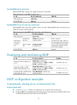
Страница 58: ...assword Required none by default NOTE To enable DLDP to operate properly make sure that DLDP authentication modes and passwords on both sides of a link are the same Resetting DLDP state After DLDP detects a unidirectional link on a port the port enters Disable state In this case DLDP prompts you to shut down the port manually or shuts down the port automatically depending on the user defined port ...

Страница 59: ...ly to the current port only configurations performed in port group view apply to all the ports in the port group Reset DLDP state dldp reset Required Displaying and maintaining DLDP To do Use the command Remarks Display the DLDP configuration of a port display dldp interface type interface number begin exclude include regular expression Available in any view Display the statistics on DLDP packets ...

Страница 60: ...Mbps and enable DLDP on the port DeviceA interface gigabitethernet 1 0 49 DeviceA GigabitEthernet1 0 49 duplex full DeviceA GigabitEthernet1 0 49 speed 1000 DeviceA GigabitEthernet1 0 49 dldp enable DeviceA GigabitEthernet1 0 49 quit Configure GigabitEthernet 1 0 50 to operate in full duplex mode and at 1000 Mbps and enable DLDP on the port DeviceA interface gigabitethernet 1 0 50 DeviceA GigabitE...

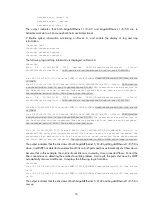
Страница 61: ...t the port shutdown mode to auto DeviceB dldp unidirectional shutdown auto 3 Verifying the configurations After the configurations are complete you can use the display dldp command to display the DLDP configuration information on ports Display the DLDP configuration information on all the DLDP enabled ports of Device A DeviceA display dldp DLDP global status enable DLDP interval 5s DLDP work mode ...

Страница 62: ...link status is DOWN Jan 18 17 36 20 190 2010 DeviceA DLDP 3 DLDP_UNIDIRECTION_AUTO Slot 1 DLDP detects a unidirectional link on port GigabitEthernet1 0 50 The transceiver has malfunction in the Tx direction or cross connected links exist between the local device and its neighbor The shutdown mode is AUTO DLDP shuts down the port Jan 15 16 54 56 040 2010 DeviceA DLDP 3 DLDP_UNIDIRECTION_AUTO_ENHANC...

Страница 63: ...GE1 0 50 GE1 0 49 GE1 0 50 GE1 0 49 GE1 0 50 GE1 0 49 GE1 0 50 Configuration procedure 1 Configuration on Device A Enable DLDP globally DeviceA system view DeviceA dldp enable Configure GigabitEthernet 1 0 49 to operate in full duplex mode and at 1000 Mbps and enable DLDP on the port DeviceA interface gigabitethernet 1 0 49 DeviceA GigabitEthernet1 0 49 duplex full DeviceA GigabitEthernet1 0 49 sp...

Страница 64: ...ll DeviceB GigabitEthernet1 0 50 speed 1000 DeviceB GigabitEthernet1 0 50 dldp enable DeviceB GigabitEthernet1 0 50 quit Set the DLDP mode to enhanced DeviceB dldp work mode enhance Set the port shutdown mode to manual DeviceB dldp unidirectional shutdown manual 3 Verifying the configurations After the configurations are complete you can use the display dldp command to display the DLDP configurati...

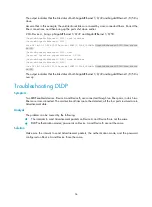
Страница 65: ...e shutdown mode is MANUAL The port needs to be shut down by the user Jan 18 18 10 38 618 2010 DeviceA DLDP 1 TrapOfUnidirectional Slot 1 h3cDLDPUnidirectionalPort DLDP detects a unidirectional link in port 17825793 Jan 18 18 10 38 618 2010 DeviceA DLDP 3 DLDP_UNIDIRECTION_MANUAL Slot 1 DLDP detects a unidirectional link on port GigabitEthernet1 0 50 The transceiver has malfunction in the Tx direct...

Страница 66: ...GigabitEthernet1 0 49 Jan 18 18 22 46 065 2010 DeviceA IFNET 3 LINK_UPDOWN GigabitEthernet1 0 49 link status is UP The output indicates that the link status of both GigabitEthernet 1 0 49 and GigabitEthernet 1 0 50 is now up Troubleshooting DLDP Symptom Two DLDP enabled devices Device A and Device B are connected through two fiber pairs in which two fibers are cross connected The unidirectional li...

Страница 67: ...d enterprise networks usually use the ring structure to improve reliability However services will be interrupted if any node in the ring network fails A ring network usually uses Resilient Packet Ring RPR or Ethernet rings RPR is high in cost as it needs dedicated hardware In contrast Ethernet ring technology is more mature and economical so it is more and more widely used in MANs and enterprise n...

Страница 68: ...ollowing states Health state All the physical links on the Ethernet ring are connected Disconnect state Some physical links on the Ethernet ring are broken As shown in Figure 13 Domain 1 contains two RRPP rings Ring 1 and Ring 2 The level of Ring 1 is set to 0 and that of Ring 2 is set to 1 Ring 1 is configured as the primary ring and Ring 2 is configured as a subring Control VLAN and data VLAN 1 ...

Страница 69: ...rimary ring and Ring 2 is a subring Device A is the master node of Ring 1 Device B Device C and Device D are the transit nodes of Ring 1 Device E is the master node of Ring 2 Device B is the edge node of Ring 2 and Device C is the assistant edge node of Ring 2 Primary port and secondary port Each master node or transit node has two ports connected to an RRPP ring one serving as the primary port an...

Страница 70: ...e master node initiates Hello packets to detect the integrity of a ring in a network Fast Hello The master node initiates Fast Hello packets to fast detect the integrity of a ring in a network Link Down The transit node the edge node or the assistant edge node initiates Link Down packets to notify the master node of the disappearance of a ring in case of a link failure Common Flush FDB The master ...

Страница 71: ...Hello packets ensuring that all nodes in the ring network are consistent in the two timer settings A transit node however cannot learn the Fast Hello timer value and the Fast Fail timer value set on the master node through received Fast Hello packets How RRPP works Polling mechanism The polling mechanism is used by the master node of an RRPP ring to check the Health state of the ring network The m...

Страница 72: ...nfigured with different protected VLANs Device A is the master node of Ring 1 in Domain 1 Device B is the master node of Ring 1 in Domain 2 With such configurations traffic of different VLANs can be transmitted on different links to achieve load balancing in the single ring network RRPP ring group In an edge node RRPP ring group only an activated subring with the lowest domain ID and ring ID can s...

Страница 73: ... master node of Ring 1 sends out Fast Hello packets periodically and determines the ring status according to whether Fast Hello packets are received before the Fast Fail timer expires implementing link status fast detection NOTE The timer resolution refers to the shortest period timer provided on an RRPP node To implement fast detection on an RRPP ring enable fast detection on the master node edge...

Страница 74: ...define an RRPP domain and configure one ring as the primary ring and the other rings as subrings Figure 16 Schematic diagram for an intersecting ring network Dual homed rings As shown in Figure 17 two or more rings are in the dual homed rings network topology with two similar common nodes between rings You only need to define an RRPP domain and configure one ring as the primary ring and the other ...

Страница 75: ...d balancing network Domain 1 Ring 1 Device A Device B Device D Device C Domain 2 Intersecting ring load balancing In an intersecting ring network you can also achieve load balancing by configuring multiple domains As shown in Figure 19 Ring 1 is the primary ring and Ring 2 is the subring in both Domain 1 and Domain 2 Domain 1 and Domain 2 are configured with different protected VLANs Device A is c...

Страница 76: ...ontrol VLANs and data VLANs for each RRPP domain and then determine the ring roles and node roles based on the traffic paths in each RRPP domain Complete the following tasks to configure RRPP Task Remarks Creating an RRPP domain Required Perform this task on all nodes in the RRPP domain Configuring control VLANs Required Perform this task on all nodes in the RRPP domain Configuring protected VLANs...

Страница 77: ...evices in the same RRPP domain must be configured with the same domain ID Make this configuration on devices you want to configure as nodes in the RRPP domain Follow these steps to create an RRPP domain To do Use the command Remarks Enter system view system view Create an RRPP domain and enter RRPP domain view rrpp domain domain id Required Configuring control VLANs Before configuring RRPP rings i...

Страница 78: ...hould be protected by the RRPP domains Perform this configuration on all nodes in the RRPP domain to be configured Follow these steps to configure protected VLANs To do Use the command Remarks Enter system view system view Enter RRPP domain view rrpp domain domain id Configure protected VLANs for the RRPP domain protected vlan reference instance instance id list Required By default no protected VL...

Страница 79: ...runk permit vlan commands see the Layer 2 LAN Switching Command Reference For more information about the undo stp enable command see the Layer 2 LAN Switching Command Reference The 802 1p priority of trusted packets on the RRPP ports must be configured so that RRPP packets take higher precedence than data packets when passing through the RRPP ports For more information about the qos trust dot1p co...

Страница 80: ...it node of the ring and specify the primary port and the secondary port ring ring id node mode transit primary port interface type interface number secondary port interface type interface number level level value Required Specifying an edge node When configuring an edge node you must first configure the primary ring before configuring the subrings Perform this configuration on a device to be confi...

Страница 81: ...type interface number Required Activating an RRPP domain To activate an RRPP domain on the current device enable the RRPP protocol and RRPP rings for the RRPP domain on the current device Perform this operation on all nodes in the RRPP domain Follow these steps to activate an RRPP domain To do Use the command Remarks Enter system view system view Enable RRPP rrpp enable Required Disabled by defaul...

Страница 82: ...bling fast detection Perform this configuration on the master node edge node and assistant edge node in the RRPP domain to be configured Follow these steps to enable fast detection To do Use the command Remarks Enter system view system view Enter RRPP domain view rrpp domain domain id Enable fast detection fast detection enable Required Disabled by default CAUTION To configure fast detection on th...

Страница 83: ...dge node and can only be configured on these two types of nodes Perform this configuration on both the edge node and the assistant edge node in an RRPP domain Follow these steps to configure an RRPP ring group To do Use the command Remarks Enter system view system view Create an RRPP ring group and enter RRPP ring group view rrpp ring group ring group id Required Assign the specified subrings to t...

Страница 84: ...set rrpp statistics domain domain id ring ring id Available in user view RRPP configuration examples Single ring configuration example Networking requirements Device A Device B Device C and Device D form RRPP domain 1 Specify the primary control VLAN of RRPP domain 1 as VLAN 4092 and specify that RRPP domain 1 protects VLANs 1 through 30 Device A Device B Device C and Device D form primary ring 1 ...

Страница 85: ...y DeviceA GigabitEthernet1 0 2 undo stp enable DeviceA GigabitEthernet1 0 2 port link type trunk DeviceA GigabitEthernet1 0 2 port trunk permit vlan 1 to 30 DeviceA GigabitEthernet1 0 2 qos trust dot1p DeviceA GigabitEthernet1 0 2 quit Create RRPP domain 1 configure VLAN 4092 as the primary control VLAN of RRPP domain 1 and configure the VLANs mapped to MSTI 1 as the protected VLANs of RRPP domain...

Страница 86: ...and configure the VLANs mapped to MSTI 1 through 32 as the protected VLANs of RRPP domain 1 DeviceB rrpp domain 1 DeviceB rrpp domain1 control vlan 4092 DeviceB rrpp domain1 protected vlan reference instance 1 Configure Device B as the transit node of primary ring 1 with GigabitEthernet 1 0 1 as the primary port and GigabitEthernet 1 0 2 as the secondary port and enable ring 1 DeviceB rrpp domain1...

Страница 87: ...port Figure 21 Network diagram for intersecting rings configuration Configuration procedure 1 Configuration on Device A Create VLANs 1 through 30 map these VLANs to MSTI 1 and activate the MST region configuration DeviceA system view DeviceA vlan 1 to 30 DeviceA stp region configuration DeviceA mst region instance 1 vlan 1 to 30 DeviceA mst region active region configuration DeviceA mst region qui...

Страница 88: ... map these VLANs to MSTI 1 and activate the MST region configuration DeviceB system view DeviceB vlan 1 to 30 DeviceB stp region configuration DeviceB mst region instance 1 vlan 1 to 30 DeviceB mst region active region configuration DeviceB mst region quit Disable physical state change suppression and STP on GigabitEthernet 1 0 1 GigabitEthernet 1 0 2 and GigabitEthernet 1 0 3 configure the ports ...

Страница 89: ...1 ring 2 enable DeviceB rrpp domain1 quit Enable RRPP DeviceB rrpp enable 3 Configuration on Device C Create VLANs 1 through 30 map these VLANs to MSTI 1 and activate the MST region configuration DeviceC system view DeviceC vlan 1 to 30 DeviceC stp region configuration DeviceC mst region instance 1 vlan 1 to 30 DeviceC mst region active region configuration DeviceC mst region quit Disable physical...

Страница 90: ...itEthernet 1 0 3 as the edge port and enable ring 2 DeviceC rrpp domain1 ring 2 node mode assistant edge edge port gigabitethernet 1 0 3 DeviceC rrpp domain1 ring 2 enable DeviceC rrpp domain1 quit Enable RRPP DeviceC rrpp enable 4 Configuration on Device D Create VLANs 1 through 30 map these VLANs to MSTI 1 and activate the MST region configuration DeviceD system view DeviceD vlan 1 to 30 DeviceD...

Страница 91: ...n configuration DeviceE mst region instance 1 vlan 1 to 30 DeviceE mst region active region configuration DeviceE mst region quit Disable physical state change suppression and STP on GigabitEthernet 1 0 1 and GigabitEthernet 1 0 2 configure the two ports as trunk ports and assign them to VLANs 1 through 30 and configure them to trust the 802 1p precedence of the received packets DeviceE interface ...

Страница 92: ... the primary ring Ring 1 Device D is the transit node of the primary ring Ring 1 Device F is the master node of the subring Ring 3 Device C is the edge node of the subring Ring 3 Device B is the assistant edge node of the subring Ring 3 Device A Device B Device C Device D and Device E form RRPP domain 2 and VLAN 105 is the primary control VLAN of the RRPP domain Device A is the master node of the ...

Страница 93: ...ssion and STP on GigabitEthernet 1 0 1 and GigabitEthernet 1 0 2 configure the two ports as trunk ports remove them from VLAN 1 and assign them to VLAN 10 and VLAN 20 and configure them to trust the 802 1p precedence of the received packets DeviceA interface gigabitethernet 1 0 1 DeviceA GigabitEthernet1 0 1 undo link delay DeviceA GigabitEthernet1 0 1 undo stp enable DeviceA GigabitEthernet1 0 1 ...

Страница 94: ...RPP domain 2 DeviceA rrpp domain 2 DeviceA rrpp domain2 control vlan 105 DeviceA rrpp domain2 protected vlan reference instance 2 Configure Device A as the master node of primary ring 1 with GigabitEthernet 1 0 2 as the master port and GigabitEthernet 1 0 1 as the secondary port and enable ring 1 DeviceA rrpp domain2 ring 1 node mode master primary port gigabitethernet 1 0 2 secondary port gigabit...

Страница 95: ...mit vlan 1 DeviceB GigabitEthernet1 0 3 port trunk permit vlan 20 DeviceB GigabitEthernet1 0 3 qos trust dot1p DeviceB GigabitEthernet1 0 3 quit Disable physical state change suppression and STP on GigabitEthernet 1 0 4 configure the port as a trunk port remove it from VLAN 1 and assign it to VLAN 10 and configure it to trust the 802 1p precedence of the received packets DeviceB interface gigabite...

Страница 96: ...main2 ring 2 node mode assistant edge edge port gigabitethernet 1 0 3 DeviceB rrpp domain2 ring 2 enable DeviceB rrpp domain2 quit Enable RRPP DeviceB rrpp enable 3 Configuration on Device C Create VLANs 10 and 20 map VLAN 10 to MSTI 1 and VLAN 20 to MSTI 2 and activate MST region configuration DeviceC system view DeviceC vlan 10 DeviceC vlan10 quit DeviceC vlan 20 DeviceC vlan20 quit DeviceC stp ...

Страница 97: ...eviceC GigabitEthernet1 0 4 undo link delay DeviceC GigabitEthernet1 0 4 undo stp enable DeviceC GigabitEthernet1 0 4 port link type trunk DeviceC GigabitEthernet1 0 4 undo port trunk permit vlan 1 DeviceC GigabitEthernet1 0 4 port trunk permit vlan 10 DeviceC GigabitEthernet1 0 4 qos trust dot1p DeviceC GigabitEthernet1 0 4 quit Create RRPP domain 1 configure VLAN 100 as the primary control VLAN ...

Страница 98: ... configuration DeviceD mst region instance 1 vlan 10 DeviceD mst region instance 2 vlan 20 DeviceD mst region active region configuration DeviceD mst region quit Disable physical state change suppression and STP on GigabitEthernet 1 0 1 and GigabitEthernet 1 0 2 configure the two ports as trunk ports remove them from VLAN 1 and assign them to VLAN 10 and VLAN 20 and configure them to trust the 802...

Страница 99: ...t and enable ring 1 DeviceD rrpp domain2 ring 1 node mode transit primary port gigabitethernet 1 0 1 secondary port gigabitethernet 1 0 2 level 0 DeviceD rrpp domain2 ring 1 enable DeviceD rrpp domain2 quit Enable RRPP DeviceD rrpp enable 5 Configuration on Device E Create VLAN 20 map VLAN 20 to MSTI 2 and activate MST region configuration DeviceE system view DeviceE vlan 20 DeviceE vlan20 quit De...

Страница 100: ...F system view DeviceF vlan 10 DeviceF vlan10 quit DeviceF stp region configuration DeviceF mst region instance 1 vlan 10 DeviceF mst region active region configuration DeviceF mst region quit Disable physical state change suppression and STP on GigabitEthernet 1 0 1 and GigabitEthernet 1 0 2 configure the two ports as trunk ports remove them from VLAN 1 and assign them to VLAN 10 and configure the...

Страница 101: ...p 1 DeviceB rrpp ring group1 domain 2 ring 2 DeviceB rrpp ring group1 domain 1 ring 3 Create RRPP ring group 1 on Device C and add subrings 2 and 3 to the RRPP ring group DeviceC rrpp ring group 1 DeviceC rrpp ring group1 domain 2 ring 2 DeviceC rrpp ring group1 domain 1 ring 3 8 Verification After the configuration use the display command to view RRPP configuration and operational information on ...

Страница 102: ...hernet 1 0 2 DeviceA GigabitEthernet1 0 2 undo link delay DeviceA GigabitEthernet1 0 2 undo stp enable DeviceA GigabitEthernet1 0 2 port link type trunk DeviceA GigabitEthernet1 0 2 port trunk permit vlan all DeviceA GigabitEthernet1 0 2 qos trust dot1p DeviceA GigabitEthernet1 0 2 quit Create RRPP domain 1 configure VLAN 4092 as the primary VLAN of RPPP domain 1 and configure the VLANs mapped to ...

Страница 103: ... DeviceB GigabitEthernet1 0 1 qos trust dot1p DeviceB GigabitEthernet1 0 1 quit DeviceB interface gigabitethernet 1 0 2 DeviceB GigabitEthernet1 0 2 undo link delay DeviceB GigabitEthernet1 0 2 undo stp enable DeviceB GigabitEthernet1 0 2 port link type trunk DeviceB GigabitEthernet1 0 2 port trunk permit vlan all DeviceB GigabitEthernet1 0 2 qos trust dot1p 3 Configuration on Device C The configu...

Страница 104: ...ble 5 Verification Use the display command to view RRPP configuration and operational information on Device A and Device D Troubleshooting Symptom When the link state is normal the master node cannot receive Hello packets and the master node unblocks the secondary port Analysis The following reasons may apply RRPP is not enabled on some nodes in the RRPP ring The domain ID or primary control VLAN ...

Страница 105: ...ed to upstream devices As shown in Figure 24 a downstream device connects to two different upstream devices Figure 24 Diagram for a dual uplink network Device A Device E Device D Device C Device B Core network Port1 Port2 Port1 Port1 Port2 Port2 Port3 Port1 Port2 Port3 Port3 Port3 Port1 Port2 Port3 User network User network Master link Slave link Smart link group A dual uplink network demonstrates...

Страница 106: ...evice C and Port1 and Port2 of Device D each form a smart link group with Port1 being active and Port2 being standby Master port slave port Master port and slave port are two port roles in a smart link group When both ports in a smart link group are up the master port preferentially transitions to the forwarding state and the slave port stays in the standby state Once the master port fails the sla...

Страница 107: ...k including devices of other vendors Flush update where a Smart Link enabled device updates its information by transmitting flush messages over the backup link to its upstream devices This mechanism requires the upstream device to be capable of recognizing Smart Link flush messages to update its MAC address forwarding entries and ARP ND entries Role preemption mechanism As shown in Figure 24 the l...

Страница 108: ...ink status Smart Link ports need to use link detection protocols When a fault is detected or cleared the link detection protocols inform Smart Link to switch over the links With the collaboration between Smart Link and the Continuity Check CC function of Connectivity Fault Detection CFD configured CFD notifies the ports of fault detection events on the basis of detection VLANs and detection ports ...

Страница 109: ...e when STP is disabled but Smart Link has not yet taken effect on a port Configuring protected VLANs for a smart link group Follow these steps to configure the protected VLANs for a smart link group To do Use the command Remarks Enter system view system view Create a smart link group and enter smart link group view smart link group group id Configure protected VLANs for the smart link group protec...

Страница 110: ...er slave Required Configuring role preemption for a smart link group Follow these steps to configure role preemption for a smart link group To do Use the command Remarks Enter system view system view Create a smart link group and enter smart link group view smart link group group id Enable role preemption preemption mode role Required Disabled by default Configure the preemption delay preemption d...

Страница 111: ... member port To do Use the command Remarks Enter system view system view Enter Ethernet port view interface interface type interface number Configure the collaboration between Smart Link and the CC function of CFD on the port port smart link group group id track cfd cc Optional By default the collaboration between Smart Link and the CC function of CFD is not configured CAUTION When configuring the...

Страница 112: ...LANs Otherwise flush messages cannot be sent properly Make sure that the control VLANs are existing VLANs and assign the ports capable of receiving flush messages to the control VLANs Displaying and maintaining Smart Link To do Use the command Remarks Display smart link group information display smart link group group id all begin exclude include regular expression Available in any view Display in...

Страница 113: ...30 DeviceC interface gigabitethernet 1 0 1 DeviceC GigabitEthernet1 0 1 shutdown DeviceC GigabitEthernet1 0 1 undo stp enable DeviceC GigabitEthernet1 0 1 port link type trunk DeviceC GigabitEthernet1 0 1 port trunk permit vlan 1 to 30 DeviceC GigabitEthernet1 0 1 quit DeviceC interface gigabitethernet 1 0 2 DeviceC GigabitEthernet1 0 2 shutdown DeviceC GigabitEthernet1 0 2 undo stp enable DeviceC...

Страница 114: ...wn DeviceD GigabitEthernet1 0 1 undo stp enable DeviceD GigabitEthernet1 0 1 port link type trunk DeviceD GigabitEthernet1 0 1 port trunk permit vlan 1 to 30 DeviceD GigabitEthernet1 0 1 quit DeviceD interface gigabitethernet 1 0 2 DeviceD GigabitEthernet1 0 2 shutdown DeviceD GigabitEthernet1 0 2 undo stp enable DeviceD GigabitEthernet1 0 2 port link type trunk DeviceD GigabitEthernet1 0 2 port t...

Страница 115: ...ceB GigabitEthernet1 0 3 port trunk permit vlan 1 to 30 DeviceB GigabitEthernet1 0 3 smart link flush enable control vlan 10 20 DeviceB GigabitEthernet1 0 3 quit 4 Configuration on Device E Create VLANs 1 through 30 DeviceE system view DeviceE vlan 1 to 30 Configure GigabitEthernet 1 0 1 GigabitEthernet 1 0 2 and GigabitEthernet 1 0 3 as trunk ports that permit VLANs 1 through 30 enable flush mess...

Страница 116: ...ations Use the display smart link group command to display the smart link group configuration on each device For example Display the smart link group configuration on Device C DeviceC display smart link group 1 Smart link group 1 information Device ID 000f e23d 5af0 Preemption mode NONE Preemption delay 1 s Control VLAN 10 Protected VLAN Reference Instance 1 Member Role State Flush count Last flus...

Страница 117: ... region configuration DeviceC system view DeviceC vlan 1 to 200 DeviceC stp region configuration DeviceC mst region instance 1 vlan 1 to 100 DeviceC mst region instance 2 vlan 101 to 200 DeviceC mst region active region configuration DeviceC mst region quit Shut down ports GigabitEthernet 1 0 1 and GigabitEthernet 1 0 2 disable STP on them and configure them as trunk ports that permit VLANs 1 thro...

Страница 118: ...eC smlk group2 port gigabitethernet 1 0 1 slave Enable role preemption in smart link group 2 enable flush message sending and configure VLAN 101 as the transmit control VLAN DeviceC smlk group2 preemption mode role DeviceC smlk group2 flush enable control vlan 101 DeviceC smlk group2 quit Bring up ports GigabitEthernet 1 0 1 and GigabitEthernet 1 0 2 DeviceC interface gigabitethernet1 0 1 DeviceC ...

Страница 119: ... control vlan 10 101 DeviceD GigabitEthernet1 0 2 quit 4 Configuration on Device A Create VLAN 1 through VLAN 200 DeviceA system view DeviceA vlan 1 to 200 Configure GigabitEthernet 1 0 1 and GigabitEthernet 1 0 2 as trunk ports and assign them to VLANs 1 through 200 enable flush message receiving on GigabitEthernet 1 0 1 and GigabitEthernet 1 0 2 and configure VLAN 10 and VLAN 101 as the receive ...

Страница 120: ...Member Role State Flush count Last flush time GigabitEthernet1 0 2 MASTER ACTVIE 5 16 37 20 2010 02 21 GigabitEthernet1 0 1 SLAVE STANDBY 1 17 45 20 2010 02 21 Use the display smart link flush command to display the flush messages received on each device For example Display the flush messages received on Device B DeviceB display smart link flush Received flush packets 5 Receiving interface of the ...

Страница 121: ...ports and adapt the up down state of downlink ports to the up down state of uplink ports triggering link switchover on the downstream device in time as shown in Figure 27 Figure 27 Monitor Link application scenario Terminology Monitor link group A monitor link group is a set of uplink and downlink ports A port can belong to only one monitor link group As shown in Figure 27 ports Port1 and Port2 of...

Страница 122: ...group contains no uplink port or all its uplink ports are down the monitor link group goes down which forces all its downlink ports down at the same time When any uplink port goes up the monitor link group goes up and brings up all its downlink ports CAUTION H3C does not recommend to manually shut down or bring up the downlink ports in a monitor link group Configuring Monitor Link Configuration pr...

Страница 123: ...t can be assigned to only one monitor link group Configure uplink ports prior to downlink ports to avoid undesired down up state changes on the downlink ports Displaying and maintaining Monitor Link To do Use the command Remarks Display monitor link group information display monitor link group group id all begin exclude include regular expression Available in any view Monitor Link configuration ex...

Страница 124: ...igabitEthernet1 0 1 port link type trunk DeviceC GigabitEthernet1 0 1 port trunk permit vlan 1 to 30 DeviceC GigabitEthernet1 0 1 quit DeviceC interface gigabitethernet 1 0 2 DeviceC GigabitEthernet1 0 2 undo stp enable DeviceC GigabitEthernet1 0 2 port link type trunk DeviceC GigabitEthernet1 0 2 port trunk permit vlan 1 to 30 DeviceC GigabitEthernet1 0 2 quit Create smart link group 1 and config...

Страница 125: ...tethernet 1 0 1 DeviceB GigabitEthernet1 0 1 port link type trunk DeviceB GigabitEthernet1 0 1 port trunk permit vlan 1 to 30 DeviceB GigabitEthernet1 0 1 smart link flush enable DeviceB GigabitEthernet1 0 1 quit DeviceB interface gigabitethernet 1 0 2 DeviceB GigabitEthernet1 0 2 port link type trunk DeviceB GigabitEthernet1 0 2 port trunk permit vlan 1 to 30 DeviceB GigabitEthernet1 0 2 smart li...

Страница 126: ...nk DeviceD mtlk group1 quit 5 Verify the configurations Use the display monitor link group command display the monitor link group information on devices For example when GigabitEthernet 1 0 2 on Device A goes down due to a link fault Check information about monitor link group 1 on Device B DeviceB display monitor link group 1 Monitor link group 1 information Group status UP Last up time 16 37 20 2...

Страница 127: ...r 3 Ethernet interface is an Ethernet interface operating in route mode For more information about the operating mode of the Ethernet interface see the Layer 2 LAN Switching Configuration Guide VRRP overview Typically as shown in Figure 29 you can configure a default route with the gateway as the next hop for every host on a network segment All packets destined to other network segments are sent o...

Страница 128: ...ither of the following modes Standard protocol mode Includes two versions VRRPv2 and VRRPv3 based on RFCs VRRPv2 is based on IPv4 and VRRPv3 is based on IPv6 The two versions implement the same functions but are applied in different network environments For more information see VRRP standard protocol mode Load balancing mode Extends the standard protocol mode and realizes load balancing For more i...

Страница 129: ...RP determines the role master or backup of each router in a VRRP group by priority A router with a higher priority is more likely to become the master VRRP priority is in the range of 0 to 255 The greater the number the higher the priority Priorities 1 to 254 are configurable Priority 0 is reserved for special uses and priority 255 for the IP address owner When a router acts as the IP address owne...

Страница 130: ...ode VRRP timers VRRP timers include VRRP advertisement interval timer and VRRP preemption delay timer VRRP advertisement interval timer The master in a VRRP group periodically sends VRRP advertisements to inform the other routers in the VRRP group that it operates properly You can adjust the interval for sending VRRP advertisements by setting the VRRP advertisement interval timer If a backup recei...

Страница 131: ...router that is ID of the VRRP group It ranges from 1 to 255 Priority Priority of the router in the VRRP group in the range 0 to 255 A greater value represents a higher priority Count IP Addrs Count IPv6 Addrs Number of virtual IPv4 or IPv6 addresses for the VRRP group A VRRP group can have multiple virtual IPv4 or IPv6 addresses Auth Type Authentication type 0 means no authentication 1 means simpl...

Страница 132: ... master and sends VRRP advertisements to start a new master election NOTE The VRRP group configuration might be different on routers and network problems might exist so multiple master routers might exist in one VRRP group These master routers will elect one master according to their priorities and IP addresses The router with the highest priority wins the election If a tie exists in the priority ...

Страница 133: ...In master backup mode only the master forwards packets When the master fails a new master is elected from the backups This mode requires only one VRRP group in which each router holds a different priority and the one with the highest priority becomes the master as shown in Figure 33 Figure 33 VRRP in master backup mode Assume that Router A is the master and therefore can forward packets to externa...

Страница 134: ...e the expected role in the group VRRP load balancing mode Overview When VRRP works in standard protocol mode only the master can forward packets and the backups are in the state of listening You can create multiple VRRP groups to share the load among multiple routers but hosts on the LAN need to be configured with different gateways thus making the configuration complicated In load balancing mode ...

Страница 135: ... MAC addresses to the routers including the master itself and the backups in the VRRP group For example as shown in Figure 35 the virtual IP address of the VRRP group is 10 1 1 1 24 Router A is the master Router B and Router C are the backups Router A assigns 000f e2ff 0011 to itself and 000f e2ff 0012 to Router B Figure 35 Allocating virtual MAC addresses 2 Upon receiving an ARP request destined ...

Страница 136: ... example as shown in Figure 37 Host A regards the virtual MAC address of Router A as the gateway MAC address so it sends packets to Router A for forwarding Host B regards the virtual MAC address of Router B as the gateway MAC address so it sends packets to Router B for forwarding Figure 37 Send packets to different routers for forwarding ...

Страница 137: ...en the weight is lower than the lower limit of failure the router cannot be capable of forwarding packets for the hosts The priority of a VF determines the VF state Among the VFs that correspond to the same virtual MAC address on different routers in the VRRP group a VF with the highest priority is in the active state and is known as the active virtual forwarder AVF which forwards packets other VF...

Страница 138: ... which is lower than that of VF 1 on Router A In this case VF 1 on both Router B and Router C acts as the LVF to listen to the status of VF 1 on Router A When VF 1 on Router A fails VF 1 on Router B and Router C elects the one with a higher priority value as the new AVF responsible for forwarding the packets destined for virtual MAC address 000f e2ff 001 1 NOTE A VF always works in preemptive mode...

Страница 139: ...col mode defines only VRRP advertisement Only the master in a VRRP group periodically sends VRRP advertisements and the backups do not send VRRP advertisements VRRP load balancing mode defines the following types of packets Advertisement VRRP advertises VRRP group state and information about the VF that is in the active state Both the master and the backups periodically send VRRP advertisements Re...

Страница 140: ...VRRP groups on the router work in the specified working mode Follow these steps to configure a VRRP working mode To do Use the command Remarks Enter system view system view Configure VRRP to work in standard protocol mode undo vrrp mode Configure VRRP to work in load balancing mode vrrp mode load balance Required Use either command By default VRRP works in standard protocol mode Specifying the typ...

Страница 141: ...ultiple interfaces of a device and the VRRP advertisements of these VRRP groups are to be sent through QinQ networks H3C recommends you to map the real MAC addresses of the interfaces to the virtual IP addresses of these VRRP groups Otherwise the VRRP advertisements of these VRRP groups cannot be sent successfully Creating a VRRP group and configuring virtual IP address When creating a VRRP group ...

Страница 142: ...ed for it In addition configurations on that VRRP group do not take effect any longer Removal of the VRRP group on the IP address owner causes IP address collision To solve the collision modify the IP address of the interface on the IP address owner first and then remove the VRRP group from the interface The virtual IP address of a VRRP group cannot be 0 0 0 0 255 255 255 255 loopback addresses no...

Страница 143: ...t need to configure it An IP address owner always works in preemptive mode Do not configure VRRP tracking for an interface or a track entry on an IP address owner The tracked interface can be a Layer 3 Ethernet interface or a VLAN interface If the state of a tracked interface changes from down or removed to up the priority of the router where the interface resides is automatically restored If the ...

Страница 144: ... the VF owner decreases by a properly specified value and becomes lower than the lower limit of failure In other words the weight of the VF owner decreases by more than 245 Configuring VRRP packet attributes Configuration prerequisites Before you configure the relevant attributes of VRRP packets create a VRRP group and configure a virtual IP address for it Configuration procedure Follow these step...

Страница 145: ...to the information center of the device where you can configure whether to output the trap information and the output destination For how to configure the information center see the Network Management and Monitoring Configuration Guide Follow these steps to enable the trap function for VRRP To do Use the command Remarks Enter system view system view Enable the trap function for VRRP snmp agent tra...

Страница 146: ...answering ND requests from hosts so that the hosts in the internal network can learn the mapping between the IPv6 address and the MAC address The following types of MAC addresses are available to be mapped to the virtual IPv6 address of a VRRP group Virtual MAC address By default a virtual MAC address is automatically created for a VRRP group when the VRRP group is created and the virtual IPv6 add...

Страница 147: ...P group later the virtual IPv6 address is added to the virtual IPv6 address list of the VRRP group NOTE H3C does not recommend you to create VRRP groups on the VLAN interface of a super VLAN because network performance might be adversely affected Configuration prerequisites Before you create a VRRP group and configure a virtual IPv6 address on an interface configure an IPv6 address for the interfa...

Страница 148: ...group on the IP address owner causes IP address collision To resolve the collision change the IPv6 address of the interface on the IP address owner first and then remove the VRRP group from the interface Configuring router priority preemptive mode and tracking function Configuration prerequisites Before you configure router priority preemptive mode and tracking function create a VRRP group and con...

Страница 149: ...lid to positive the priority of the router where the track entry is configured is automatically restored Configuring VF tracking Configuration prerequisites Before you configure the VF tracking function create a VRRP group and configure a virtual IPv6 address for it Configuration procedure VRRP works in load balancing mode Suppose that the VF is configured to monitor a track entry When the state o...

Страница 150: ...r Layer 3 Ethernet interface view interface interface type interface number Configure the authentication mode and authentication key when the VRRP groups send or receive VRRP packets vrrp ipv6 vrid virtual router id authentication mode simple key Optional Authentication is not performed by default Configure the time interval for the master in the VRRP group to send VRRP advertisement vrrp ipv6 vri...

Страница 151: ...e in user view IPv4 based VRRP configuration examples This section provides these configuration examples Single VRRP group configuration example VRRP interface tracking configuration example VRRP with multiple VLANs configuration example VRRP load balancing mode configuration example Single VRRP group configuration example Network requirements Host A wants to access Host B on the Internet using 20...

Страница 152: ... 5 2 Configure Switch B Configure VLAN 2 SwitchB system view SwitchB vlan 2 SwitchB Vlan2 port gigabitethernet 1 0 5 SwitchB vlan2 quit SwitchB interface vlan interface 2 SwitchB Vlan interface2 ip address 202 38 160 2 255 255 255 0 Create VRRP group 1 and set its virtual IP address to 202 38 160 1 1 1 SwitchB Vlan interface2 vrrp vrid 1 virtual ip 202 38 160 111 Set Switch B to work in preemptive...

Страница 153: ...d information of the VRRP group on Switch B When Switch A fails the detailed information of VRRP group 1 on Switch B is displayed SwitchB Vlan interface2 display vrrp verbose IPv4 Standby Information Run Mode Standard Run Method Virtual MAC Total number of virtual routers 1 Interface Vlan interface2 VRID 1 Adver Timer 1 Admin Status Up State Master Config Pri 100 Running Pri 100 Preempt Mode Yes D...

Страница 154: ...y packets sent from Host A to Host B are forwarded by Switch A If VLAN interface 3 through which Switch A connects to the Internet is not available packets sent from Host A to Host B are forwarded by Switch B To prevent attacks to the VRRP group by illegal users who use spoofed packets configure the authentication mode as plain text to authenticate the VRRP packets in VRRP group 1 and specify the ...

Страница 155: ...me the master SwitchA Vlan interface2 vrrp vrid 1 track interface vlan interface 3 reduced 30 2 Configure Switch B Configure VLAN 2 SwitchB system view SwitchB vlan 2 SwitchB vlan2 port gigabitethernet 1 0 5 SwitchB vlan2 quit SwitchB interface vlan interface 2 SwitchB Vlan interface2 ip address 202 38 160 2 255 255 255 0 Create a VRRP group 1 and set its virtual IP address to 202 38 160 1 1 1 Swi...

Страница 156: ...02 38 160 1 The output shows that in VRRP group 1 Switch A is the master Switch B is the backup and packets sent from Host A to Host B are forwarded by Switch A If interface VLAN interface 3 through which Switch A connects to the Internet is not available you can still ping Host B on Host A To view the detailed information of the VRRP group use the display vrrp verbose command If VLAN interface 3 ...

Страница 157: ...38 160 100 25 as their default gateway and hosts in VLAN 3 use 202 38 160 200 25 as their default gateway Switch A and Switch B belong to both VRRP group 1 and VRRP group 2 The virtual IP address of VRRP group 1 is 202 38 160 100 25 and that of VRRP group 2 is 202 38 160 200 25 In VRRP group 1 Switch A has a higher priority than Switch B In VRRP group 2 Switch B has a higher priority than Switch A...

Страница 158: ...55 128 Create a VRRP group 2 and set its virtual IP address to 202 38 160 200 SwitchA Vlan interface3 vrrp vrid 2 virtual ip 202 38 160 200 2 Configure Switch B Configure VLAN 2 SwitchB system view SwitchB vlan 2 SwitchB vlan2 port gigabitethernet 1 0 5 SwitchB vlan2 quit SwitchB interface vlan interface 2 SwitchB Vlan interface2 ip address 202 38 160 2 255 255 255 128 Create a VRRP group 1 and se...

Страница 159: ...erface Vlan interface3 VRID 2 Adver Timer 1 Admin Status Up State Backup Config Pri 100 Running Pri 100 Preempt Mode Yes Delay Time 0 Auth Type None Virtual IP 202 38 160 200 Master IP 202 38 160 131 Display the detailed information of the VRRP group on Switch B SwitchB Vlan interface3 display vrrp verbose IPv4 Standby Information Run Mode Standard Run Method Virtual MAC Total number of virtual ro...

Страница 160: ...on the LAN can access external networks through another gateway VRRP group 1 works in load balancing mode to make good use of network resources Configure a track entry on Switch A Switch B and Switch C respectively to monitor their own VLAN interface 3 When the interface on Switch A Switch B or Switch C fails the weight of the corresponding switch decreases so that another switch with a higher wei...

Страница 161: ...try 1 making the weight of Switch A decrease by more than 245 250 in this example when track entry 1 turns to negative In such a case another router with a higher weight can take over SwitchA interface vlan interface 2 SwitchA Vlan interface2 vrrp vrid 1 weight track 1 reduced 250 2 Configure Switch B Configure VLAN 2 SwitchB system view SwitchB vlan 2 SwitchB vlan2 port gigabitethernet 1 0 5 Swit...

Страница 162: ...2 quit Create track entry 1 to associate with the physical status of VLAN interface 3 on Switch C When the track entry becomes negative it means that the interface fails SwitchC track 1 interface vlan interface 3 Configure the VFs to monitor track entry 1 making the weight of Switch C decrease by more than 245 250 in this example when track entry 1 turns to negative In such a case another router w...

Страница 163: ...k Information Track Object 1 State Positive Weight Reduced 250 Display the detailed information of VRRP group 1 on Switch B SwitchB Vlan interface2 display vrrp verbose IPv4 Standby Information Run Mode Load Balance Run Method Virtual MAC Total number of virtual routers 1 Interface Vlan interface2 VRID 1 Adver Timer 1 Admin Status Up State Backup Config Pri 110 Running Pri 110 Preempt Mode Yes Del...

Страница 164: ...by Information Run Mode Load Balance Run Method Virtual MAC Total number of virtual routers 1 Interface Vlan interface2 VRID 1 Adver Timer 1 Admin Status Up State Backup Config Pri 100 Running Pri 100 Preempt Mode Yes Delay Time 5 Auth Type None Virtual IP 10 1 1 1 Member IP List 10 1 1 4 Local Backup 10 1 1 2 Master 10 1 1 3 Backup Forwarder Information 3 Forwarders 1 Active Config Weight 255 Run...

Страница 165: ...un Mode Load Balance Run Method Virtual MAC Total number of virtual routers 1 Interface Vlan interface2 VRID 1 Adver Timer 1 Admin Status Up State Master Config Pri 120 Running Pri 120 Preempt Mode Yes Delay Time 5 Auth Type None Virtual IP 10 1 1 1 Member IP List 10 1 1 2 Local Master 10 1 1 3 Backup 10 1 1 4 Backup Forwarder Information 3 Forwarders 0 Active Config Weight 255 Running Weight 5 Fo...

Страница 166: ... 01 State Active Virtual MAC 000f e2ff 0011 Take Over Owner ID 0000 5e01 1101 Priority 85 Active local Redirect Time 93 secs Time out Time 1293 secs Forwarder 02 State Listening Virtual MAC 000f e2ff 0012 Learnt Owner ID 0000 5e01 1103 Priority 85 Active 10 1 1 3 Forwarder 03 State Active Virtual MAC 000f e2ff 0013 Owner Owner ID 0000 5e01 1105 Priority 255 Active local Forwarder Weight Track Info...

Страница 167: ...t Owner ID 0000 5e01 1103 Priority 127 Active 10 1 1 3 Forwarder 03 State Active Virtual MAC 000f e2ff 0013 Owner Owner ID 0000 5e01 1105 Priority 255 Active local Forwarder Weight Track Information Track Object 1 State Positive Weight Reduced 250 The output shows that when the timeout timer expires the VF corresponding to virtual MAC address 000f e2ff 001 1 is removed and does not forward the pac...

Страница 168: ...ority is higher than that of Switch C IPv6 based VRRP configuration examples This section provides these configuration examples Single VRRP group configuration example VRRP interface tracking configuration example VRRP with multiple VLANs configuration example VRRP load balancing mode configuration example Single VRRP group configuration example Network requirements Switch A and Switch B belong to...

Страница 169: ...v6 vrid 1 virtual ip 1 10 Set the priority of Switch A in VRRP group 1 to 1 10 which is higher than that of Switch B so that Switch A can become the master SwitchA Vlan interface2 vrrp ipv6 vrid 1 priority 110 Configure Switch A to work in preemptive mode so that it can become the master whenever it works normally and configure the preemption delay as five seconds to avoid frequent status switchov...

Страница 170: ...v6 verbose command Display the detailed information of VRRP group 1 on Switch A SwitchA Vlan interface2 display vrrp ipv6 verbose IPv6 Standby Information Run Mode Standard Run Method Virtual MAC Total number of virtual routers 1 Interface Vlan interface2 VRID 1 Adver Timer 100 Admin Status Up State Master Config Pri 110 Running Pri 110 Preempt Mode Yes Delay Time 5 Auth Type None Virtual IP FE80 ...

Страница 171: ...After Switch A resumes normal operation use the display vrrp ipv6 verbose command to display the detailed information of VRRP group 1 on Switch A SwitchA Vlan interface2 display vrrp ipv6 verbose IPv6 Standby Information Run Mode Standard Run Method Virtual MAC Total number of virtual routers 1 Interface Vlan interface2 VRID 1 Adver Timer 100 Admin Status Up State Master Config Pri 110 Running Pri...

Страница 172: ...1 0 5 SwitchA vlan2 quit SwitchA interface vlan interface 2 SwitchA Vlan interface2 ipv6 address fe80 1 link local SwitchA Vlan interface2 ipv6 address 1 1 64 Create a VRRP group 1 and set its virtual IPv6 addresses to FE80 10 and 1 10 SwitchA Vlan interface2 vrrp ipv6 vrid 1 virtual ip fe80 10 link local SwitchA Vlan interface2 vrrp ipv6 vrid 1 virtual ip 1 10 Set the priority of Switch A in VRRP...

Страница 173: ...ip 1 10 Set the authentication mode for VRRP group 1 to simple and authentication key to hello SwitchB Vlan interface2 vrrp ipv6 vrid 1 authentication mode simple hello Set the VRRP advertisement interval to 400 centiseconds SwitchB Vlan interface2 vrrp ipv6 vrid 1 timer advertise 400 Configure Switch B to work in preemptive mode so that Switch B can become the master after the priority of Switch ...

Страница 174: ...N interface 3 on Switch A is not available you can still ping Host B on Host A To view the detailed information of the VRRP group use the display vrrp ipv6 verbose command When interface VLAN interface 3 on Switch A is not available the detailed information of VRRP group 1 on Switch A is displayed SwitchA Vlan interface2 display vrrp ipv6 verbose IPv6 Standby Information Run Mode Standard Run Meth...

Страница 175: ...ents Switch A and Switch B belong to both VRRP group 1 and VRRP group 2 The virtual IPv6 addresses of VRRP group 1 are 1 10 64 and FE80 10 and those of VRRP group 2 are 2 10 64 and FE90 10 Hosts in VLAN 2 learn 1 10 64 as their default gateway and hosts in VLAN 3 learn 2 10 64 as their default gateway through RA messages sent by the switches In VRRP group 1 Switch A has a higher priority than Swit...

Страница 176: ... Vlan interface2 quit Configure VLAN 3 SwitchA vlan 3 SwitchA vlan3 port gigabitethernet 1 0 6 SwitchA vlan3 quit SwitchA interface vlan interface 3 SwitchA Vlan interface3 ipv6 address fe90 1 link local SwitchA Vlan interface3 ipv6 address 2 1 64 Create VRRP group 2 and set its virtual IPv6 addresses to FE90 10 and 2 10 SwitchA Vlan interface3 vrrp ipv6 vrid 2 virtual ip fe90 10 link local Switch...

Страница 177: ...n VRRP group 2 SwitchB Vlan interface3 vrrp ipv6 vrid 2 priority 110 Enable Switch B to send RA messages so that hosts in VLAN 3 can learn the default gateway address SwitchB Vlan interface3 undo ipv6 nd ra halt 3 Verify the configuration To verify the configuration use the display vrrp ipv6 verbose command Display the detailed information of the VRRP group on Switch A SwitchA Vlan interface3 disp...

Страница 178: ...he Internet through Switch A in VRRP group 2 Switch A is the backup Switch B is the master and hosts with the default gateway of 2 10 64 accesses the Internet through Switch B VRRP load balancing mode configuration example Network requirements Switch A Switch B and Switch C belong to VRRP group 1 with the virtual IPv6 addresses of FE80 10 and 1 10 Hosts on network segment 1 64 learn 1 10 as their ...

Страница 179: ...al IPv6 addresses as FE80 10 and 1 10 SwitchA interface vlan interface 2 SwitchA Vlan interface2 ipv6 address fe80 1 link local SwitchA Vlan interface2 ipv6 address 1 1 64 SwitchA Vlan interface2 vrrp ipv6 vrid 1 virtual ip fe80 10 link local SwitchA Vlan interface2 vrrp ipv6 vrid 1 virtual ip 1 10 Set the priority of Switch A in VRRP group 1 to 120 which is higher than that of Switch B and that o...

Страница 180: ... interface2 vrrp ipv6 vrid 1 virtual ip fe80 10 link local SwitchB Vlan interface2 vrrp ipv6 vrid 1 virtual ip 1 10 Set the priority of Switch B in VRRP group 1 to 1 10 which is higher than that of Switch C so that Switch B can become the master when Switch A fails SwitchB Vlan interface2 vrrp ipv6 vrid 1 priority 110 Set Switch B to work in preemptive mode and set the preemption delay to five sec...

Страница 181: ...ce 3 on Switch C When the track entry becomes negative it means that the interface fails SwitchC track 1 interface vlan interface 3 Configure the VFs to monitor track entry 1 making the weight of Switch C decrease by more than 245 250 in this example when track entry 1 turns to negative In such a case another router with a higher weight can take over SwitchC interface vlan interface 2 SwitchC Vlan...

Страница 182: ...ed 250 Display the detailed information of VRRP group 1 on Switch B SwitchB Vlan interface2 display vrrp ipv6 verbose IPv6 Standby Information Run Mode Load Balance Run Method Virtual MAC Total number of virtual routers 1 Interface Vlan interface2 VRID 1 Adver Timer 100 Admin Status Up State Backup Config Pri 110 Running Pri 110 Preempt Mode Yes Delay Time 5 Auth Type None Virtual IP FE80 10 1 10 ...

Страница 183: ... Mode Load Balance Run Method Virtual MAC Total number of virtual routers 1 Interface Vlan interface2 VRID 1 Adver Timer 100 Admin Status Up State Backup Config Pri 100 Running Pri 100 Preempt Mode Yes Delay Time 5 Auth Type None Virtual IP FE80 10 1 10 Member IP List FE80 3 Local Backup FE80 1 Master FE80 2 Backup Forwarder Information 3 Forwarders 1 Active Config Weight 255 Running Weight 255 Fo...

Страница 184: ...Run Mode Load Balance Run Method Virtual MAC Total number of virtual routers 1 Interface Vlan interface2 VRID 1 Adver Timer 100 Admin Status Up State Master Config Pri 120 Running Pri 120 Preempt Mode Yes Delay Time 5 Auth Type None Virtual IP FE80 10 1 10 Member IP List FE80 1 Local Master FE80 2 Backup FE80 3 Backup Forwarder Information 3 Forwarders 0 Active Config Weight 255 Running Weight 5 F...

Страница 185: ...warder 01 State Active Virtual MAC 000f e2ff 4011 Take Over Owner ID 0000 5e01 1101 Priority 85 Active local Redirect Time 93 secs Time out Time 1293 secs Forwarder 02 State Listening Virtual MAC 000f e2ff 4012 Learnt Owner ID 0000 5e01 1103 Priority 85 Active FE80 2 Forwarder 03 State Active Virtual MAC 000f e2ff 4013 Owner Owner ID 0000 5e01 1105 Priority 255 Active local Forwarder Weight Track ...

Страница 186: ...f 4012 Learnt Owner ID 0000 5e01 1103 Priority 127 Active FE80 2 Forwarder 03 State Active Virtual MAC 000f e2ff 4013 Owner Owner ID 0000 5e01 1105 Priority 255 Active local Forwarder Weight Track Information Track Object 1 State Positive Weight Reduced 250 The output shows that when the timeout timer expires the VF corresponding to virtual MAC address 000f e2ff 401 1 is removed and does not forwa...

Страница 187: ...ts priority is higher than that of Switch C Troubleshooting VRRP The screen frequently displays error prompts Analysis This error is probably caused by Inconsistent configuration of the devices in the VRRP group A device is attempting to send illegitimate VRRP packets Solution In the first case modify the configuration In the latter case resort to non technical measures Multiple masters are presen...

Страница 188: ...rms of number of virtual IP addresses virtual IP addresses advertisement interval and authentication Frequent VRRP state transition Analysis The VRRP advertisement interval is set too short Solution Increase the interval to send VRRP advertisement or introduce a preemption delay ...

Страница 189: ...mission Deploying only one device even with high reliability in such a network risks a single point of failure and cannot meet the requirement as shown in Figure 47 Figure 47 Network with one device deployed Internet Device Host A Host B Internal network The stateful failover feature was introduced to meet the requirement Stateful failover involves service backup The operating procedure of statefu...

Страница 190: ... stateful failover Introduction to stateful failover states The stateful failover states include Silence Indicates that the device has just started or is transiting from synchronization state to independence state Independence Indicates that the silence timer has expired but no failover link is established Synchronization Indicates that the device has completed state negotiation with the other dev...

Страница 191: ...e after the configurations take effect For a device providing portal services you need to perform further configurations on the device before it can automatically back up portal service information to the backup device For more information see the Security Configuration Guide Enabling stateful failover When you enable stateful failover with the dhbk enable backup type dissymmetric path symmetric p...

Страница 192: ...her services for the backup VLAN such as MAC VLAN or Voice VLAN otherwise the operation of stateful failover may be affected The interfaces assigned to a backup VLAN can forward other packets besides stateful failover packets Displaying and maintaining stateful failover To do Use the command Remarks Display the running status and related information of stateful failover display dhbk status begin e...

Страница 193: ...nfigure Device B Create VLAN 100 DeviceB system view DeviceB vlan 100 Assign GigabitEthernet 1 0 1 to VLAN 100 DeviceB vlan100 port gigabitethernet 1 0 1 DeviceB vlan100 quit Assign GigabitEthernet 1 0 2 to VLAN 100 Because Device B and Device C may exchange packets of multiple VLANs configure GigabitEthernet 1 0 2 as a trunk port and permit packets of VLAN 100 to pass DeviceB interface gigabiteth...

Страница 194: ...et 1 0 1 and GigabitEthernet 1 0 3 Do not configure other functions or parameters on a failover interface To run NAT on two failover devices you need to configure two identical NAT address pools for each device but the higher priority address pool on a device must be different from that on the other otherwise a conflict may occur during backup For example you can configure two NAT address pools 10...

Страница 195: ...cause a large quantity of data to be dropped The hello mechanism is unacceptable for delay sensitive services such as voice service Moreover this detection method largely relies on the routing protocol Other detection methods Some protocols provide dedicated detection mechanisms which however cannot be deployed for inter system communications Bidirectional forwarding detection BFD provides a singl...

Страница 196: ...rce addresses 3 BFD uses the information to establish BFD sessions Figure 52 BFD fault detection on OSPF routers BFD fault detection 1 BFD detects a link failure 2 BFD clears the neighbor session 3 BFD notifies the protocol of the failure 4 The protocol terminates the neighborship on the link 5 If a backup link is available the protocol will use it to forward packets NOTE No detection time resolut...

Страница 197: ...erate in one of the following BFD operating modes Asynchronous mode both endpoints periodically send BFD control packets to each other BFD considers that the session is down if it receives no BFD control packets within a specific interval Demand mode no BFD control packets are exchanged after the session is established It is assumed that the endpoints have another way to verify connectivity to eac...

Страница 198: ...Reserved for future use State Sta Current BFD session state Its value can be 0 for AdminDown 1 for Down 2 for Init and 3 for Up Poll P If set the transmitting system is requesting verification of connectivity or of a parameter change If clear the transmitting system is not requesting verification Final F If set the transmitting system is responding to a received BFD control packet that had the Pol...

Страница 199: ...tween received BFD echo packets that this system is capable of supporting If this value is zero the transmitting system does not support receipt of BFD echo packets Auth Type The authentication type in use if the Authentication Present A bit is set Auth Len The length in bytes of the authentication section including the Auth Type and Auth Len fields Supported features OSPF For more information see...

Страница 200: ... the destination port number for multi hop BFD control packets bfd multi hop destination port port number Optional 4784 by default Configure the source IP address of echo packets bfd echo source ip ip address Optional The source IP address should not be on the same network segment as any local interface s IP address Otherwise a large number of ICMP redirect packets may be sent from the peer result...

Страница 201: ...inimum interval for transmitting BFD control packets on Router A and the minimum interval for receiving BFD control packets on Router B The actual transmitting interval on Router B is 300 milleseconds which is the greater value between the minimum interval for transmitting BFD control packets on Router B and the minimum interval for receiving BFD control packets on Router A The actual detection ti...

Страница 202: ...play information about BFD enabled interfaces display bfd interface verbose begin exclude include regular expression Available in any view Display information about enabled BFD debugging display bfd debugging switches begin exclude include regular expression Available in any view Display BFD session information display bfd session slot slot number all verbose verbose begin exclude include regular ...

Страница 203: ...mance and informs the track module of detection results The track module sends the detection results to the associated application module and the application module takes actions when the tracked object changes its state Figure 53 Collaboration through the track module Application modules Policy based routing Static routing VRRP Detection modules NQA BFD Interface management Sends the detection re...

Страница 204: ...ty can preempt as the master to forward packets When the uplink interface recovers if the track module immediately notifies the original master to restore its priority the master will immediately forward packets however the uplink route has not been recovered yet which may result in packet forwarding failure Then configure the track module to notify the application modules of the track entry statu...

Страница 205: ... the track module that the tracked object is unreachable Then the track module sets the track entry to the Negative state If the specified threshold is not reached the NQA module tells the track module that the tracked object functions normally The track module then sets the track entry to the Positive state For more information about NQA see the Network Management and Monitoring Configuration Gui...

Страница 206: ... track track entry number bfd echo interface interface type interface number remote ip remote ip local ip local ip delay negative negative time positive positive time Required No track entry is created by default NOTE When associating track with BFD do not configure the virtual IP address of a VRRP group as the local or remote address of a BFD session Associating track with interface management Th...

Страница 207: ... responsibility of the failed master When VRRP works in standard protocol mode or load balancing mode associate the track module with the VRRP group to implement the following objects Change the priority of a router according to the status of the uplink If there is a fault on the uplink of the router the VRRP group cannot be aware of the uplink failure If the router is the master hosts in the LAN ...

Страница 208: ...id virtual router id virtual ip virtual address Required No VRRP group is created by default Associate a track entry with the VRRP VF vrrp ipv6 vrid virtual router id weight track track entry number reduced weight reduced Required By default no track entry is specified for a VF This command is supported when VRRP works in both standard protocol mode and load balancing mode However this function ta...

Страница 209: ... the track entry shows that the reachability of the next hop of the static route is unknown and the static route is valid Follow these steps to associate track with static routing To do Use the command Remarks Enter system view system view ip route static dest address mask mask length next hop address vpn instance d vpn instance name next hop address track track entry number preference preference ...

Страница 210: ...e state of the track entry shows that the object is not available and the apply clause is invalid The Invalid state of the track entry shows that the apply clause is valid The following objects can be associated with a track entry Next hop Default next hop Configuration prerequisites Before you associate track with PBR create a policy or a policy node and configure the match criteria Configuration...

Страница 211: ...rded through Switch A When VRRP finds that there is a fault on the uplink of Switch A through NQA packets from Host A to Host B are forwarded through Switch B Figure 54 Network diagram for VRRP track NQA collaboration configuration Host A Switch A Switch B Virtual IP address 10 1 1 10 24 Vlan int2 10 1 1 1 24 Vlan int2 10 1 1 2 24 Host B 10 1 1 3 24 20 1 1 1 24 Internet Vlan int3 10 1 2 1 24 Vlan ...

Страница 212: ...1 to 1 10 SwitchA Vlan interface2 vrrp vrid 1 priority 110 Set the authentication mode of VRRP group 1 to simple and the authentication key to hello SwitchA Vlan interface2 vrrp vrid 1 authentication mode simple hello Configure the master to send VRRP packets at an interval of five seconds SwitchA Vlan interface2 vrrp vrid 1 timer advertise 5 Configure Switch A to work in preemptive mode and set t...

Страница 213: ...tchB Vlan interface2 display vrrp verbose IPv4 Standby Information Run Mode Standard Run Method Virtual MAC Total number of virtual routers 1 Interface Vlan interface2 VRID 1 Adver Timer 5 Admin Status Up State Backup Config Pri 100 Running Pri 100 Preempt Mode Yes Delay Time 5 Auth Type Simple Key hello Virtual IP 10 1 1 10 Master IP 10 1 1 1 The output shows that in VRRP group 1 Switch A is the ...

Страница 214: ...tween Switch A and Switch C the priority of Switch A decreases to 80 Switch A becomes the backup and Switch B becomes the master Packets from Host A to Host B are forwarded through Switch B Configuring BFD for a VRRP backup to monitor the master Network requirements As shown in Figure 55 Switch A and Switch B belong to VRRP group 1 the virtual IP address of which is 192 168 0 10 The default gatewa...

Страница 215: ...VRRP group 1 to 1 10 SwitchA Vlan interface2 vrrp vrid 1 virtual ip 192 168 0 10 SwitchA Vlan interface2 vrrp vrid 1 priority 110 SwitchA Vlan interface2 return 3 Configure BFD on Switch B Configure the source address of BFD echo packets as 10 10 10 10 SwitchB system view SwitchB bfd echo source ip 10 10 10 10 4 Create the track entry to be associated with the BFD session on Switch B Create track ...

Страница 216: ...C 0000 5e00 0101 Master IP 192 168 0 101 Display the detailed information of VRRP group 1 on Switch B SwitchB display vrrp verbose IPv4 Standby Information Run Mode Standard Run Method Virtual MAC Total number of virtual routers 1 Interface Vlan interface2 VRID 1 Adver Timer 1 Admin Status Up State Backup Config Pri 100 Running Pri 100 Preempt Mode Yes Delay Time 0 Auth Type None Virtual IP 192 16...

Страница 217: ... interface2 VRID 1 Adver Timer 1 Admin Status Up State Master Config Pri 100 Running Pri 100 Preempt Mode Yes Delay Time 0 Auth Type None Virtual IP 192 168 0 10 Virtual MAC 0000 5e00 0101 Master IP 192 168 0 102 VRRP Track Information Track Object 1 State Negative Switchover The output shows that when BFD detects that Switch A fails it notifies VRRP through the track module to change the status o...

Страница 218: ...ssion on Switch A Create track entry 1 to be associated with the BFD session to check whether the uplink device with the IP address 1 1 1 2 is reachable SwitchA track 1 bfd echo interface vlan interface 3 remote ip 1 1 1 2 local ip 1 1 1 1 4 Configure VRRP on Switch A Create VRRP group 1 and configure the virtual IP address of the group as 192 168 0 10 configure the priority of Switch A in VRRP gr...

Страница 219: ... 101 VRRP Track Information Track Object 1 State Positive Pri Reduced 20 Display the information of track entry 1 on Switch A SwitchA display track 1 Track ID 1 Status Positive Duration 0 days 0 hours 4 minutes 10 seconds Notification delay Positive 0 Negative 0 in seconds Reference object BFD session Packet type Echo Interface Vlan interface2 Remote IP 1 1 1 2 Local IP 1 1 1 1 Display the detaile...

Страница 220: ...rs 1 Interface Vlan interface2 VRID 1 Adver Timer 1 Admin Status Up State Backup Config Pri 110 Running Pri 90 Preempt Mode Yes Delay Time 0 Auth Type None Virtual IP 192 168 0 10 Master IP 192 168 0 102 VRRP Track Information Track Object 1 State Negative Pri Reduced 20 Display the detailed information of VRRP group 1 on Switch B SwitchB display vrrp verbose IPv4 Standby Information Run Mode Stan...

Страница 221: ... real time If the master route is unavailable the backup route takes effect and Switch A forwards packets to 30 1 1 0 24 through Switch C Similarly Switch D is the default gateway of the hosts in segment 30 1 1 0 24 Two static routes to 20 1 1 0 24 exist on Switch D with the next hop being Switch B and Switch C respectively These two static routes back up each other where The static route with Swi...

Страница 222: ...ntry 1 specifying that five consecutive probe failures trigger the static routing track NQA collaboration SwitchA nqa admin test icmp echo reaction 1 checked element probe fail threshold type consecutive 5 action type trigger only SwitchA nqa admin test icmp echo quit Start NQA probes SwitchA nqa schedule admin test start time now lifetime forever Configure track entry 1 and associate it with reac...

Страница 223: ...ency 100 Configure reaction entry 1 specifying that five consecutive probe failures trigger the static routing track NQA collaboration SwitchD nqa admin test icmp echo reaction 1 checked element probe fail threshold type consecutive 5 action type trigger only SwitchD nqa admin test icmp echo quit Start NQA probes SwitchD nqa schedule admin test start time now lifetime forever Configure track entry...

Страница 224: ...Reference object NQA entry admin test Reaction 1 Display the routing table of Switch A SwitchA display ip routing table Routing Tables Public Destinations 10 Routes 10 Destination Mask Proto Pre Cost NextHop Interface 10 1 1 0 24 Direct 0 0 10 1 1 1 Vlan2 10 1 1 1 32 Direct 0 0 127 0 0 1 InLoop0 10 2 1 0 24 Static 60 0 10 1 1 2 Vlan2 10 3 1 0 24 Direct 0 0 10 3 1 1 Vlan3 10 3 1 1 32 Direct 0 0 127...

Страница 225: ...d 30 1 1 0 24 Configure static routes on these routers so that the two segments can communicate with each other and configure route backup to improve reliability of the network Switch A is the default gateway of the hosts in segment 20 1 1 0 24 Two static routes to 30 1 1 0 24 exist on Switch A with the next hop being Switch B and Switch C respectively These two static routes back up each other wh...

Страница 226: ...c 30 1 1 0 24 10 3 1 3 preference 80 Configure the source address of BFD echo packets as 10 10 10 10 SwitchA bfd echo source ip 10 10 10 10 Configure track entry 1 and associate it with the BFD session Check whether Switch A can be interoperated with the next hop of static route Switch B SwitchA track 1 bfd echo interface vlan interface 2 remote ip 10 2 1 2 local ip 10 2 1 1 3 Configure Switch B C...

Страница 227: ...NextHop Interface 10 2 1 0 24 Direct 0 0 10 2 1 1 Vlan2 10 2 1 1 32 Direct 0 0 127 0 0 1 InLoop0 10 3 1 0 24 Direct 0 0 10 3 1 1 Vlan3 10 3 1 1 32 Direct 0 0 127 0 0 1 InLoop0 20 1 1 0 24 Direct 0 0 20 1 1 1 Vlan5 20 1 1 1 32 Direct 0 0 127 0 0 1 InLoop0 30 1 1 0 24 Static 60 0 10 2 1 2 Vlan2 127 0 0 0 8 Direct 0 0 127 0 0 1 InLoop0 127 0 0 1 32 Direct 0 0 127 0 0 1 InLoop0 The output shows the BF...

Страница 228: ...still communicate with the hosts in 30 1 1 0 24 SwitchA ping a 20 1 1 1 30 1 1 1 PING 30 1 1 1 56 data bytes press CTRL_C to break Reply from 30 1 1 1 bytes 56 Sequence 1 ttl 254 time 2 ms Reply from 30 1 1 1 bytes 56 Sequence 2 ttl 254 time 1 ms Reply from 30 1 1 1 bytes 56 Sequence 3 ttl 254 time 1 ms Reply from 30 1 1 1 bytes 56 Sequence 4 ttl 254 time 2 ms Reply from 30 1 1 1 bytes 56 Sequence...

Страница 229: ... 1 1 10 24 Vlan int2 10 1 1 1 24 Vlan int2 10 1 1 2 24 Host B 10 1 1 3 24 20 1 1 1 24 Internet Vlan int3 10 1 2 1 24 Vlan int3 10 1 3 1 24 Vlan int3 10 1 3 2 24 Vlan int3 10 1 2 2 24 Switch C Switch D Configuration procedure 1 Create VLANs and assign ports to the VLANs and configure the IP address of each VLAN interface as shown in Figure 59 The configuration procedure is omitted 2 Configure a tra...

Страница 230: ...10 Virtual MAC 0000 5e00 0101 Master IP 10 1 1 1 VRRP Track Information Track Object 1 State Positive Pri Reduced 30 Display detailed information about VRRP group 1 on Switch B SwitchB Vlan interface2 display vrrp verbose IPv4 Standby Information Run Mode Standard Run Method Virtual MAC Total number of virtual routers 1 Interface Vlan interface2 VRID 1 Adver Timer 1 Admin Status Up State Backup Co...

Страница 231: ...ed 30 After shutting down the uplink interface on Switch A display detailed information about VRRP group 1 on Switch B SwitchB Vlan interface2 display vrrp verbose IPv4 Standby Information Run Mode Standard Run Method Virtual MAC Total number of virtual routers 1 Interface Vlan interface2 VRID 1 Adver Timer 1 Admin Status Up State Master Config Pri 100 Running Pri 100 Preempt Mode Yes Delay Time 0...

Страница 232: ...LAN 180 Configuring the Ethernet OAM connection detection timers 10 Configuring VRRP for IPv4 127 Configuring VRRP for IPv6 134 Creating an RRPP domain 65 D Displaying and maintaining BFD 190 Displaying and maintaining CFD 29 Displaying and maintaining DLDP 47 Displaying and maintaining Ethernet OAM configuration 14 Displaying and maintaining Monitor Link 1 1 1 Displaying and maintaining RRPP 72 D...

Страница 233: ...44 Setting the port shutdown mode 45 Smart Link configuration examples 100 Smart Link configuration task list 96 Smart Link overview 93 Stateful failover configuration example 180 T Track configuration examples 199 Track configuration task list 192 Track overview 191 Troubleshooting 92 Troubleshooting DLDP 54 Troubleshooting VRRP 175 V VRRP load balancing mode 122 VRRP overview 1 15 VRRP standard ...

Отзывы: