


181
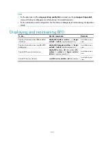
Figure 50
Network diagram for stateful failover
Configuration procedure
1.
Configure Device A.
# Create VLAN 100.
<DeviceA> system-view
[DeviceA] vlan 100
# Assign GigabitEthernet 1/0/1 to VLAN 100.
[DeviceA-vlan100] port gigabitethernet 1/0/1
[DeviceA-vlan100] quit
# Specify VLAN 100 as a backup VLAN.
[DeviceA] dhbk vlan 100
# Enable symmetric-path mode stateful failover.
[DeviceA] dhbk enable backup-type symmetric-path
2.
Configure Device B.
# Create VLAN 100.
<DeviceB> system-view
[DeviceB] vlan 100
# Assign GigabitEthernet 1/0/1 to VLAN 100.
[DeviceB-vlan100] port gigabitethernet 1/0/1
[DeviceB-vlan100] quit
# Assign GigabitEthernet 1/0/2 to VLAN 100.
Because Device B and Device C may exchange packets of multiple VLANs, configure GigabitEthernet
1/0/2 as a trunk port and permit packets of VLAN 100 to pass.
[DeviceB] interface gigabitethernet 1/0/2
[DeviceB-GigabitEthernet1/0/2] port link-type trunk
[DeviceB-GigabitEthernet1/0/2] port trunk permit vlan 100
Please wait... Done.
3.
The configurations on Device C are similar to those on Device B (omitted).