


206
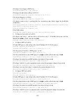
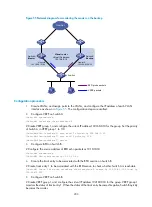
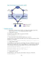
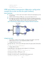
Figure 56
Network diagram for monitoring uplinks using BFD
Internet
Master
uplink device
Backup
uplink device
Uplink
Virtual router
Virtual IP address:
192.168.0.10
Vlan-int2
192.168.0.101/24
Vlan-int2
192.168.0.102/24
Switch A
Master
Switch B
Backup
Vlan-int3
1.1.1.1/24
Vlan-int3
1.1.1.2/24
L2 switch
Uplink
VRRP packets
BFD probe packets
Configuration procedure
1.
Create VLANs, and assign ports to the VLANs, and configure the IP address of each VLAN
interface as shown in
. The configuration procedure is omitted.
2.
Configure BFD on Switch A.
# Configure the source address of BFD echo packets as 10.10.10.10.
<SwitchA> system-view
[SwitchA] bfd echo-source-ip 10.10.10.10
3.
Create a track entry to be associated with the BFD session on Switch A.
# Create track entry 1 to be associated with the BFD session to check whether the uplink device with the
IP address 1.1.1.2 is reachable.
[SwitchA] track 1 bfd echo interface vlan-interface 3 remote ip 1.1.1.2 local ip 1.1.1.1
4.
Configure VRRP on Switch A
# Create VRRP group 1, and configure the virtual IP address of the group as 192.168.0.10; configure the
priority of Switch A in VRRP group 1 as 110; configure VRRP group 1 to monitor the status of track entry
1. When the status of the track entry becomes Negative, the priority of Switch A decreases by 20.
[SwitchA] interface vlan-interface 2
[SwitchA-Vlan-interface2] vrrp vrid 1 virtual-ip 192.168.0.10
[SwitchA-Vlan-interface2] vrrp vrid 1 priority 110
[SwitchA-Vlan-interface2] vrrp vrid 1 track 1 reduced 20
[SwitchA-Vlan-interface2] return
5.
Configure VRRP on Switch B
# Create VRRP group 1, and configure the virtual IP address of the group as 192.168.0.10.
<SwitchB> system-view