

5-3
Planning IRF topology and connections
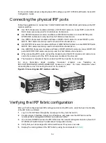
Connect the IRF member switches through IRF ports, the logical interfaces for the connections
between IRF member switches. Each IRF member switch has two IRF ports: IRF-port 1 and IRF-port
2. To use an IRF port, you must bind a minimum of one physical port to it.
When connecting two neighboring IRF member switches, you must connect the physical ports of
IRF-port 1 on one switch to the physical ports of IRF-port 2 on the other switch.
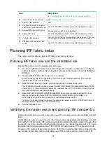
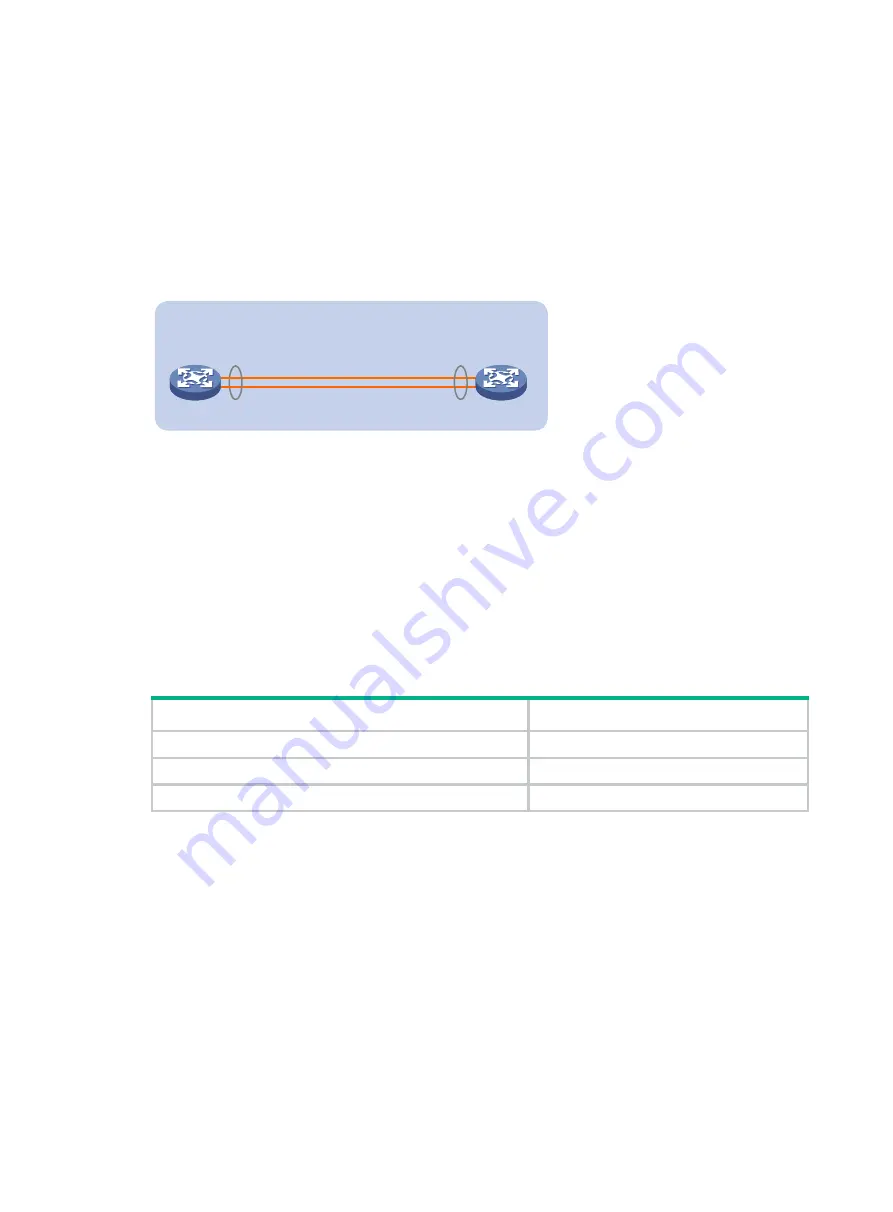
A two-member IRF fabric must use the daisy chain topology.
Figure5-2 Daisy chain topology
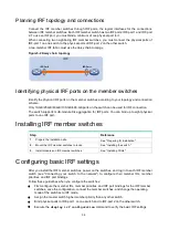
Identifying physical IRF ports on the member switches
Identify the physical IRF ports on the member switches according to your topology and connection
scheme.
Only 10-GE/25-GE/40-GE/100-GE/400-GE ports on the switch can be used for IRF connection.
The switch supports multi-module link aggregation for IRF ports. You can bind up to eight physical
ports to one IRF port.
Installing IRF member switches
Step
Reference
1.
Prepare the installation site.
See "Preparing for installation."
2.
Mount the IRF member switches to racks.
See "Installing the switch."
3.
Install modules on IRF member switches.
See "Installing FRUs."
Configuring basic IRF settings
After you install the IRF member switches, power on the switches, and log in to each IRF member
switch (see "Connecting your switch to the network") to configure their member IDs, member
priorities, and IRF port bindings.
Follow these guidelines when you configure the switches:
•
First configure the member IDs, member priorities, and IRF port bindings for the IRF member
switches, save the configuration, connect the member switches, and change the operating
mode of the switches to IRF mode.
•
Assign the master switch higher member priority than any other switch.
•
Bind physical ports to IRF-port 1 on one switch and to IRF-port 2 on the other switch.
•
Execute the
display irf configuration
command to verify the basic IRF settings.
IRF-Port1
IRF-Port2
IRF
Содержание S12500G-AF Series
Страница 32: ...3 15 Figure3 16 Connecting the grounding cable to a grounding strip 1 2 4 3 6 5 ...
Страница 49: ...4 16 Figure4 16 Connecting an SFP DAC cable 1 Pull latch 2 Connector 1 2 ...
Страница 92: ...A 12 FigureA 14 Example of a device label ...
Страница 104: ...C 6 FigureC 5 Securing the chassis to the pallet base S12504G AF switch 1 1 2 2 1 ...


