


4-14
CAUTION:
•
Be careful not to touch the golden plating on a transceiver module during the installation process.
•
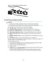
To avoid network cable damage and signal loss, do not strain or tangle a network cable.
•
Make sure the transceiver module is aligned correctly with the target port before pushing it into
the port.
•
Make sure the two module ends of a network cable are compatible with the ports into which they
will be inserted.
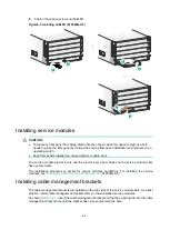
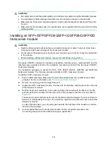
Installing an SFP+/SFP/SFP28/QSFP+/QSFP28/QSFP-DD
transceiver module
CAUTION:
•
Read the following instructions before you install a transceiver module. Failure to follow these
instructions might cause damage to the transceiver module.
•
Do not remove the dust plug from the transceiver module if you are not to connect an optical fiber
to the module.
•
Before installing a transceiver module, remove the optical fiber (if any) from it.
Two types of QSFP+ transceiver modules are available. One type uses a metal pull latch and the
other type uses a plastic pull latch. The installation procedure is similar for the two types of QSFP+
transceiver modules.
The installation procedure is similar for SFP+, SFP, SFP28, QSFP+, QSFP28, and QSFP-DD
transceiver modules. The following procedure installs an SFP+ transceiver module.
To install an SFP+ transceiver module:
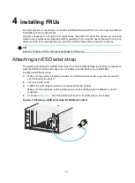
1.
Wear an ESD wrist strap. Make sure the wrist strap makes good skin contact and is reliably
grounded. For more information, see "
."
2.
Remove the dust plug from the target fiber port.
3.
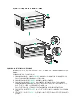
Unpack the SFP+ transceiver module. It comes with the bail latch catching the knob on the top
of the transceiver module.
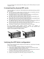
4.
Hold the transceiver module by its two sides and align the module with the fiber port. Gently
push the transceiver module into the port until it is firmly seated in the fiber port, as shown in
Transceiver modules and fiber ports have disorientation rejection designs. If you cannot insert a
transceiver module easily into a port, the orientation might be wrong. Remove and reorient the
transceiver module.
In case of limited space, you can gently push against the front face of the transceiver module
instead of the two sides.
5.
Connect optical fibers to the transceiver module. For the connection procedure, see
"Connecting the switch to the network through an optical fiber."
Содержание S12500G-AF Series
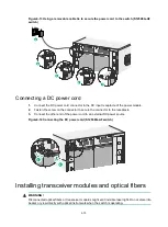
Страница 32: ...3 15 Figure3 16 Connecting the grounding cable to a grounding strip 1 2 4 3 6 5 ...
Страница 49: ...4 16 Figure4 16 Connecting an SFP DAC cable 1 Pull latch 2 Connector 1 2 ...
Страница 92: ...A 12 FigureA 14 Example of a device label ...
Страница 104: ...C 6 FigureC 5 Securing the chassis to the pallet base S12504G AF switch 1 1 2 2 1 ...


