


3-4
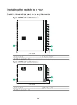
Model
Chassis depth
Rack requirements
•
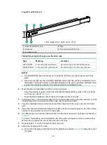
Total depth
—1016 mm (40 in) when the
LSXM104XFANH fan trays are installed:
102 mm (4.02 in) from the rack-facing
surface of the mounting brackets to the front
ends of the cable management brackets
914 mm (35.98 in) from the rack-facing
surface of the mounting brackets to the fan
tray handles at the chassis rear
NOTE:
As a best practice, use a rack that has a single door at the front.
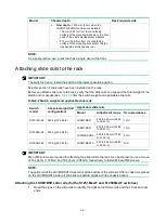
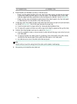
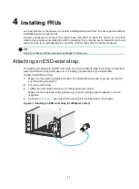
Attaching slide rails to the rack
IMPORTANT:
The switch is heavy. Install the switch at the lowest possible position.
Skip this section if slide rails have been installed on the rack.
Before you attach slide rails to the rack, verify that the slide rails can support the total weight of the
switch and its accessories.
lists the switch weight and applicable slide rails.
Table3-2 Switch weight and applicable slide rails
Switch
model
Chassis weight (full
configuration)
Applicable slide rails
Model
Adjustment range
Occupied space
S12516G-AF
360 kg (793.65 lb)
LSXM1BSR
630 to 900 mm (24.80
to 35.43 in)
1 RU
S12508G-AF
200 kg (440.92 lb)
LSXM1BSR
630 to 900 mm (24.80
to 35.43 in)
1 RU
LSTM2KSGD0
500 to 800 mm (19.69
to 31.50 in)
2 RU
S12504G-AF
115 kg (253.53 lb)
LSVM1BSR10
630 to 850 mm (24.80
to 33.46 in)
N/A
IMPORTANT:
M4 or M6 screws are required for attaching the slide rails to the rack. As a best practice, use a torque
of 12 kgf-cm (1.18 Nm) and 30 kgf-cm (2.94 Nm) respectively to fasten M4 and M6 screws.
NOTE:
The guide rail of the LSVM1BSR10 side rail is at the bottom of the slide rail. After a chassis is placed
on the LSVM1BSR10 side rail, the slide rail bottom aligns with the chassis bottom.
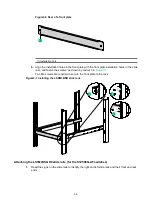
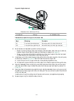
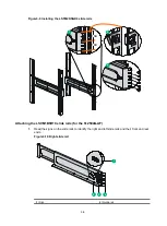
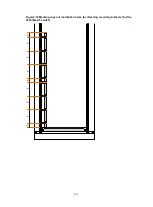
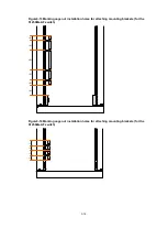
Attaching the LSXM1BSR slide rails (for the S12516G-AF and S12508G-AF switches)
1.
Read the signs on the slide rails to identify the right and left slide rails and their front and rear
ends.
Содержание S12500G-AF Series
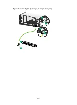
Страница 32: ...3 15 Figure3 16 Connecting the grounding cable to a grounding strip 1 2 4 3 6 5 ...
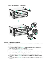
Страница 49: ...4 16 Figure4 16 Connecting an SFP DAC cable 1 Pull latch 2 Connector 1 2 ...
Страница 92: ...A 12 FigureA 14 Example of a device label ...
Страница 104: ...C 6 FigureC 5 Securing the chassis to the pallet base S12504G AF switch 1 1 2 2 1 ...


