background image

Using the Operating Panel (Continued)

Menu structure

At the top of the menu structure is the MAIN MENU. For a station configured as a Mobile Station 
it is called MAIN MENU MOB, for a station configured as Fixed Station MAIN MENU FIX, and for a 
Beacon it is called MAIN MENU BCN.
From the main menu a selection can be made from a maximum of six categories by keying-in the 
number adjacent to the category. The following display page types are distinguished:

• 

Menu pages

• 

Data pages

• 

Modify pages

• 

Instruction pages

Menu pages

Menu pages display a number of categories the operator can choose from by keying-in the 
number shown adjacent to the categories. Apart from the Main Menu pages already referred to, 
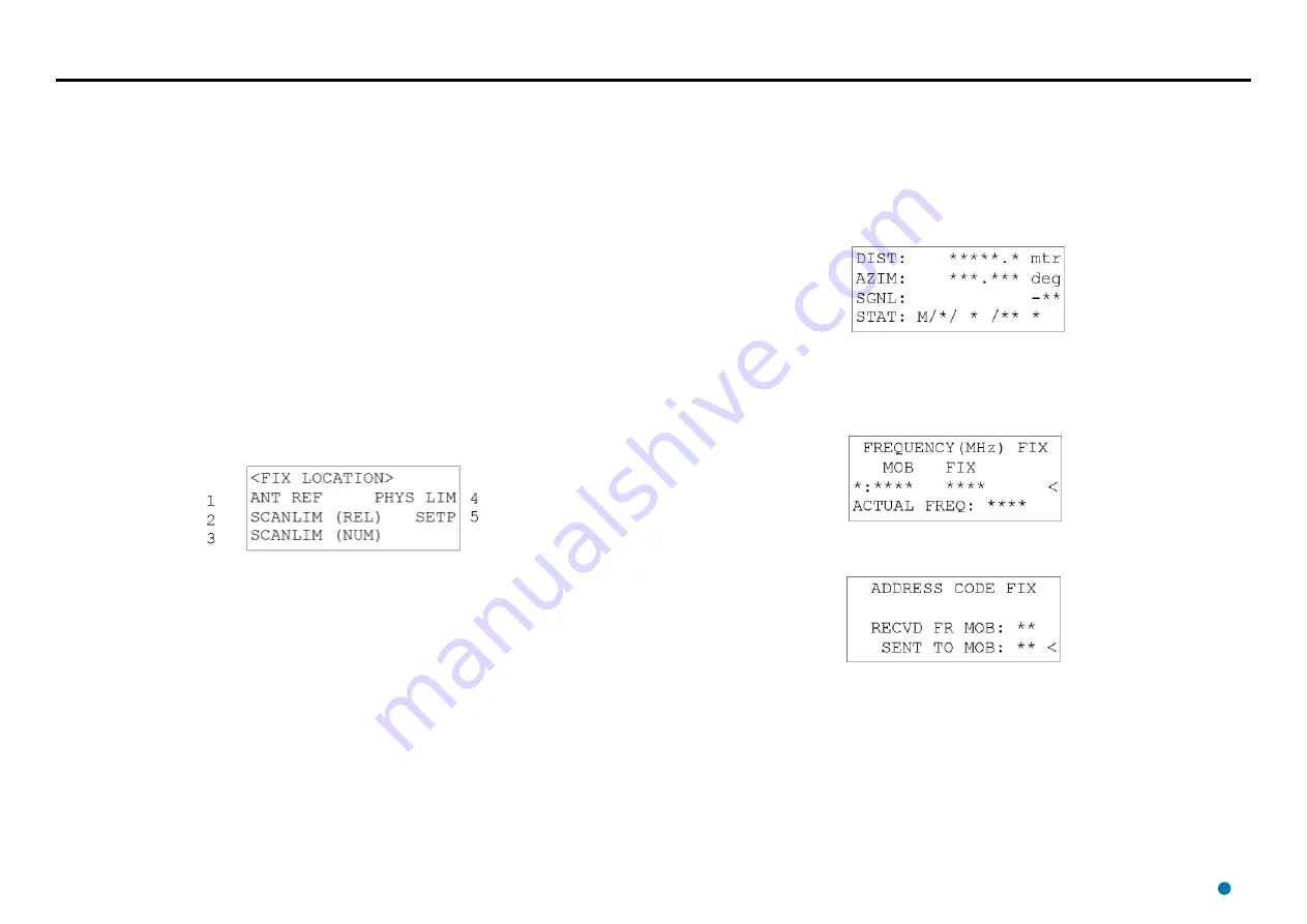
there are several other menu pages. An example of such a menu page is given below.

Example of a menu page

In this example there is a choice of five categories. Pressing “1” selects the instruction page for 
the setting of the antenna (azimuth) reference. Pressing “2” selects the instruction page to set the 
auto search left and right scan limits by turning the antenna to these limits. Pressing “3” selects 
the modify page for the setting of the numerical values of the auto search left and right scan limits. 
Pressing “4” selects the instruction page to set the physical left and right limits of the antenna. 
Pressing “5” selects the modify page for entering an azimuth value the antenna should turn to (set 
point).

Data pages

Data pages show Artemis data and /or parameters which cannot be changed, at least not through 
these pages. A particular category may contain more than one data page. For example: the 
category OPERATE in the Fixed Station menu structure contains three different data display pages. 
The first of these pages is shown below. Subsequent pages are selected by pressing the Next key.

Example of data page

Modify pages

Modify pages enable the operator to read and/or change the parameters shown on these pages. 
Some pages have a restricted number of values, from which a choice is made by pressing the 

and 

key until the required value is showing. Other parameters require a numerical value to be 

entered.

Example of a modify page (parameter value selection)

Example of a modify page (numerical input)


46

Содержание Artemis Mk6

Страница 1: ...rine Ltd 5 Tiber Way Meridian Business Park Leicester LE19 1QP UK T 44 116 229 2600 E sales guidance eu com Artemis Mk6 Installer s Guide featuring Artemis Service Interface www guidance eu com www ma...

Страница 2: ...herwise without the prior written consent of the Owner Windows is a trademark of Microsoft Corporation All other brand or product names are trademarks or registered trademarks of their respective comp...

Страница 3: ...release of Artemis Mk6 Installer s Guide 28 06 2016 94 0441 4 B Artemis Mk6 Installer s Guide 14 10 2016 94 0441 4 C Artemis Mk6 Installer s Guide 08 02 2017 94 0441 4 D Artemis Mk6 Installer s Guide...

Страница 4: ...Types of Computer 29 To Uninstall the Artemis Control Software 29 To Install the Artemis Control Software 29 Configuring the Artemis System Using the Artemis Service Interface 31 To open the Service...

Страница 5: ...introduction to the Artemis system The System Layout section on page 8 describes possible arrangements of the system on board a vessel Installing the Sensors on page 12 takes you through the installa...

Страница 6: ...nce the system is in operation This is an optional diagnostic aid System Overview Artemis Control Software The following applications run on the Artemis Control PC usually mounted on the bridge near t...

Страница 7: ...ation measures the Azimuth and reports it to the Mobile Station The Azimuth is the horizontal angle between a reference direction and the Mobile Station with its vertex at the Fixed Station Beacon Uni...

Страница 8: ...s of the system on a vessel It contains the following pages Cable Routing Diagram Serial Communications page 9 Cable Routing Diagram Ethernet Communications page 10 Cable Routing Diagrams Processor an...

Страница 9: ...r Cable DP Instrument Room Bridge Mast Emergency Breaker Box See page 11 for processor and monitor options 5A Connection Box PC Power Cable Monitor Power Cable RS232 to RS422 Converter Marine Processo...

Страница 10: ...processor and monitor options 5A Connection Box PC Power Cable Monitor Power Cable Marine Processor Data Cable Ethernet Cable Power Cable 220 240V AC 50 60 Hz Note The Ethernet cable connecting the se...

Страница 11: ...er 20 0211 4 Optional brackets Hatteland Mounting Bracket Part Number 24 0259 4 Hatteland VESA Bracket for Wall or Ceiling Part Number 24 0258 4 Power Cable Processor and Monitor Hatteland Panel PC In...

Страница 12: ...Artemis sensors and contains the following pages General Considerations page 13 Dimensions of Base Unit page 14 External Connections to an Artemis Sensor page 15 Installing a Mobile Station page 16 In...

Страница 13: ...oint be on or parallel to the centre line of the vessel see below Sensor Clearance To facilitate 360 antenna rotation a cylindrical space of 1400mm diameter with a vertical depth of 300mm around the c...

Страница 14: ...Dimensions of Base Unit View from Above View from Side View from Beneath Dimensions are expressed in mm 14...

Страница 15: ...o an Artemis Sensor An Artemis sensor can communicate with the Control PC using either Ethernet or RS422 Refer to Re Configuring the Sensor Communications Type on page 48 if you need to change from on...

Страница 16: ...other obstacles Mounting the Mobile Station Take measures to prevent falling down from the mast or other heights Use a safety harness The antenna unit should be mounted On a torsion free stand or bra...

Страница 17: ...angle measured by the encoder should be related to a reference direction To compute the vessel s heading from the angle of the Mobile antenna the relative Mobile antenna bearing and the azimuth as rec...

Страница 18: ...The antenna can only be turned by hand if the servo control mode is OPEN LOOP or if the operating mode Menu 262 is IDL idle or STB standby In Configuration mode Menu 5 the operating mode of the anten...

Страница 19: ...horizon This influence tends not to be important for the Artemis Mk6 system because the maximum range of the system is generally less than the radio horizon even with low antenna positions Reflection...

Страница 20: ...e best combination of frequency pairs is pair 0 for system 1 and pair 1 for system 2 while these pairs give the largest difference between the frequencies of the Mobile Stations To avoid influencing e...

Страница 21: ...r MAIN MENU BCN appears 4 Press 5 CONFIG The following page appears If the second line reads MOB or BCN 5 Press Enter the cursor starts blinking 6 Press the or key until it reads FIX 7 Press Enter to...

Страница 22: ...ing page appears Note The left auto search scan limit cannot lie beyond the confiured left end limit The antenna stops when the left end limit has been reached 21 Using the key and the 0 key to stop t...

Страница 23: ...wed then press the key to change ON to OFF and press Enter again to confirm Otherwise press the key to go to the parameter GYRO CMPSAT gyro compensation 39 Press Enter and then press the key to change...

Страница 24: ...bracket with three holes See General Considerations on page 13 for the required dimensions The U shape allows the beacon to be slid in the bracket rather than lowering it from above In this way it ta...

Страница 25: ...the following page appears Where can have the following values If the frequency pair showing is not the desired frequency pair 9 Press Enter the cursor starts blinking 10 Press the or key until the d...

Страница 26: ...r and address code the antenna of the Mobile Station will lock onto the Beacon and distance to the Beacon will be available at the Mobile Station If the parameter CONF PRTCTED was set to OFF Beacon pa...

Страница 27: ...3 Marine Processor and Display Installation Sheet For a Hatteland Panel PC 94 0466 4 Hatteland Panel PC Installation Sheet The following pages explain how to install the client software Installing Art...

Страница 28: ...Setup window 6 When prompted click on the Restart button After the restart the Artemis Dashboard Setup window reappears 7 When prompted click on the Restart button The uninstallation process for the D...

Страница 29: ...ck on Programs and Features 3 In the list of installed programs right click on Artemis Dashboard on a touchscreen monitor touch and hold 4 Click on the Uninstall option in the context menu 5 Click on...

Страница 30: ...etwork Configuration page 34 Configuring the DP Output page 35 Configuring System Parameters page 36 Information Tabs page 37 The Service Interface is usually connected to the mobile station of an Art...

Страница 31: ...g to communications as follows Artemis Manager The state of the connection between the ASI and the Artemis Manager Connected or Not Connected Take Command Relinquish Command This button allows the use...

Страница 32: ...imit Right These define the horizontal sector in which the local unit normally operates and through which the antenna rotates when in Auto Search mode see below The Scan Left Limit sets the anti clock...

Страница 33: ...cy Pair Address Code the model of the Remote Station and whether it is Floating or Fixed 6 Click the Add button The name of the new station is now included in the list of known Remote Stations To Sele...

Страница 34: ...To Make Changes to the Network Configuration 1 Click on the Network Config tab of the Service Interface 2 Click the Disconnect button for the type of communication that you wish to modify 3 Click the...

Страница 35: ...already done 3 Select Output Channel A B C or D 4 Click Edit 5 Click Apply to save the changes or Cancel to discard 35 The main purpose of an Artemis system is to provide positioning data to the DP D...

Страница 36: ...be edited 6 Click Apply to save the changes or Cancel to discard If whilst editing parameters from one group you wish to monitor one or two parameters from other groups this can be done using the ind...

Страница 37: ...cal station The Alarms Tab This contains a list of possible alarms and the current status of each The About Tab Contains version information for the Artemis Control Software contact details for Guidan...

Страница 38: ...Artemis Dashboard This section explains how to set up the Artemis Dashboard software It contains the following pages Start Up and Shut Down page 39 Using the On Screen Keyboard page 40 Display Options...

Страница 39: ...This reveals the Guidance Home Menu which contains different sets of buttons depending whether the Dashboard is in command and whether it is tracking a Remote Station Buttons are explained below Disc...

Страница 40: ...you selected this option during installation of the Dashboard Otherwise the OSK can be enabled and disabled by clicking F11 or by clicking Enable On Screen Keyboard Disable On Screen Keyboard on the D...

Страница 41: ...ake it brighter 5 Alternatively use the keyboard shortcut F6 or the Day Night Mode button in the Dashboard Hotkeys menu to switch between Day View and Night View Screen Layout Mode By default the main...

Страница 42: ...ontains the following appendices DP Message Formats page 43 Using the Operating Panel page 45 Re Configuring the Sensor Communications Type page 48 System Specifications page 49 Installation Checklist...

Страница 43: ...D Byte Bit 7 4 Bit 3 0 1 Azimuth x 100 Azimuth x 10 2 Azimuth x 1 Azimuth x 0 1 3 Azimuth x 0 01 Azimuth x 0 001 4 Range x 10000 Range x 1000 5 Range x 100 Range x 10 6 0000 Range x 1 7 1111 1111 ASCI...

Страница 44: ...ne Feed 0x0Ah ASCII 22 Character 1 Range x 10000 2 Range x 1000 3 Range x 100 4 Range x 10 5 Range x 1 6 Range x 0 1 7 Space 8 Bearing x 100 9 Bearing x 10 10 Bearing x 1 11 Bearing x 0 1 12 Space 13...

Страница 45: ...eacon The operating panel may also be used during service to check or alter the settings of Mobile and Fixed Stations and Beacons For a Mobile Station the operating panel is only useful for the alignm...

Страница 46: ...auto search left and right scan limits by turning the antenna to these limits Pressing 3 selects the modify page for the setting of the numerical values of the auto search left and right scan limits P...

Страница 47: ...ion pages the last instruction page also shows N in the bottom right hand corner In this case pressing Next causes a return to the sub menu page above Pressing the Menu key makes the operating panel d...

Страница 48: ...rom the power supply before removing the cover Take electrostatic precautions prior to touching printed circuit boards 1 Disconnect the sensor from the power supply 2 Remove the bottom cover 3 Identif...

Страница 49: ...cy 0 02 standard deviation Dimensions and Weights Antenna 1248 x 206 x 176 5mm approx 5kg Antenna Unit 366 x 500mm 32 8kg Re usable container for Antenna Unit 520 x 650 x 590mm l x w x h Re usable con...

Страница 50: ...MHz Radiated power 100 mW max 100 mW max 100 mW max Polarisation Vertical Vertical Vertical Range With omni directional antenna type AT 120 10m 2 500m With semi omni directional antenna type AT 010 10...

Страница 51: ...rol PC Correctly located and fastened Cables correctly installed and fastened Correctly installed routed to avoid power cabling Cables Cables fastened correctly Cables have service loops Installation...

Страница 52: ...n Bearing offset set mobile station only Azimuth reference set fixed station only Protect configuration set Auto recovery set Remote station parameters entered as required Function and Acceptance Chec...

Страница 53: ...P Format 43 ASCII 17 DP Format 44 ASCII 22 DP Format 44 Auto Search 32 Azimuth 22 32 49 B BCD DP Format 43 Beacon 7 24 45 50 Bearing 32 BEV Mode 41 C Clients Tab 37 Communications Type 48 Control Soft...

Страница 54: ......

Отзывы: