Bit Pad Two 24
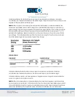
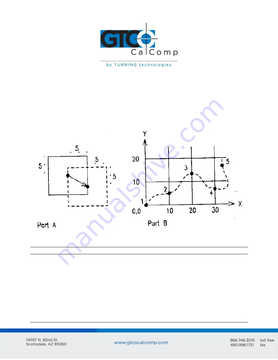
Here’s a description of how Increment Mode works: last report issued becomes the center
of an imaginary square whose sides are twice the increment value. The cursor can move
anywhere inside the imaginary square without a report being issued. As soon as the
increment is satisfied along either axis, the Bit Pad Two transmits the actual X and Y
coordinates of the point. The new point becomes the center of a new, imaginary square.
Example:
Part A shows the imaginary square created around each report point; the
increment is five. Part B shows the reports issued as the cursor or stylus travels across the
tablet; the increment is 10.
The five points issued in Part B are numbered in order.
Point
Report
Description
1
2
3
(0,0)
(10,5)
(20,13)
Only X is satisfied. The actual value of Y is transmitted.
No point is transmitted between points 2 and 3 because the cursor
or stylus did not move ten resolution counts in either the X or Y
directions.
The increment is satisfied from the last point along the X axis only;
the Bit Pad Two issues the new report.
Содержание BIT PAD TWO DATA
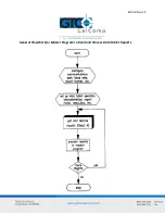
Страница 14: ...Bit Pad Two 14 General Flowchart for Master Program to Read and Process Data Tablet Reports...
Страница 15: ...Bit Pad Two 15 Detail A Get and Decode Reports Subroutine...
Страница 16: ...Bit Pad Two 16 Detail B Data Input Subroutine...
Страница 34: ...Bit Pad Two 34...
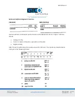
Страница 42: ...Bit Pad Two 42 Appendix B ASCII Conversion Chart...
Страница 43: ...Bit Pad Two 43...
Страница 44: ...Bit Pad Two 44...
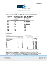
Страница 46: ...Bit Pad Two 46 Switch Settings DIP Switch 1...
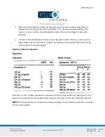
Страница 47: ...Bit Pad Two 47 Switch Settings DIP Switch 3...


