


4.3. Lens Mounting
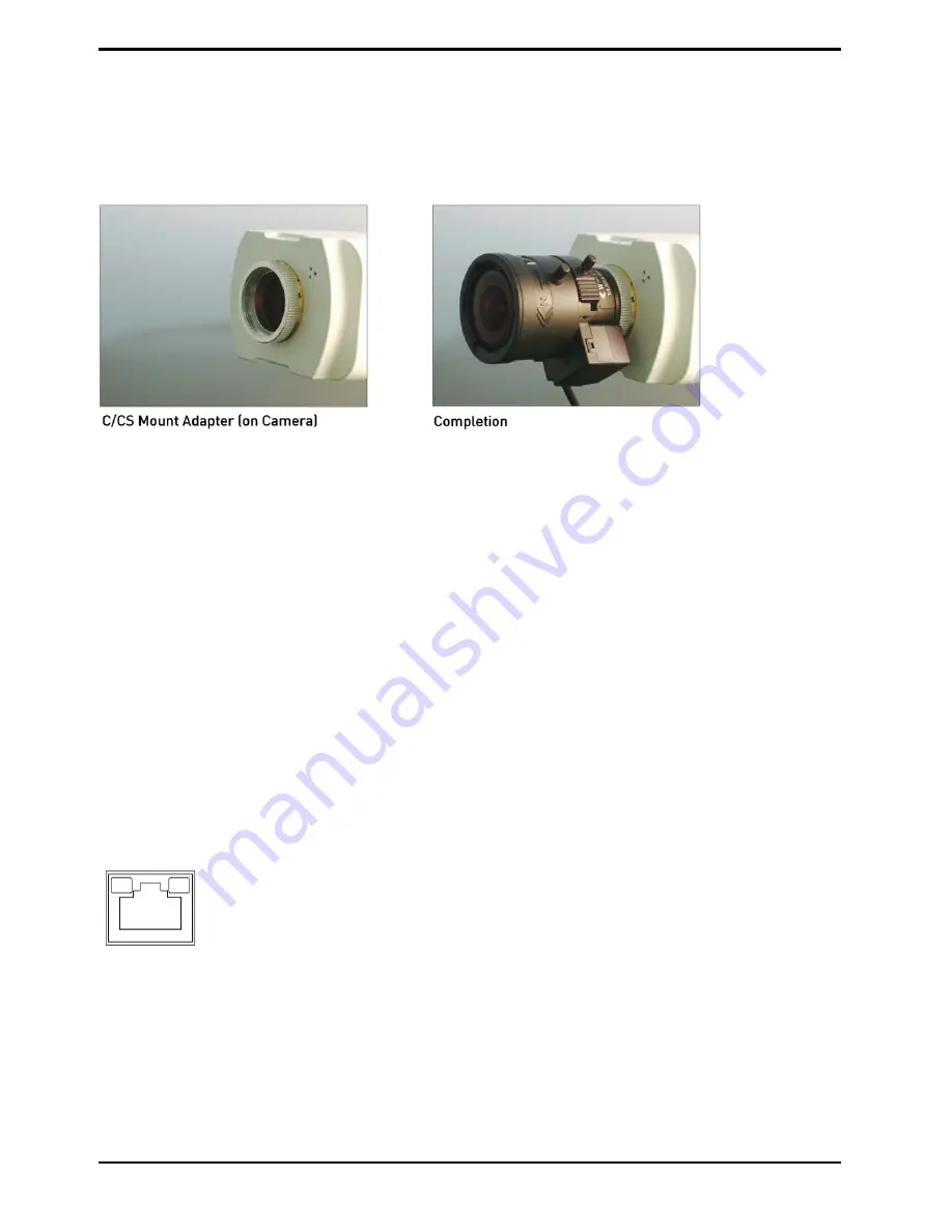
Lens Mounting for C/CS Mount Lens Model:
It is possible to attach all CS-Mount lenses with manual or DC controlled iris on the camera. Please remove the
camera’s plastic covering first and then attach the CS-Mount lens onto the camera. If you would like to use a C-
Mount lens, you need a 5 mm C/CS Mount Adapter between the camera and the C-Mount lens, as shown in the
illustration below.
4.4. Power Connection
Power Connection for GCI-K1503B
and GCI-G0509B:
Please refer to section 4.1. Camera Overview for power wiring. Additionally, if using PoE, make sure Power
Sourcing Equipment (PSE) is in use in the network.
Power connection for GCI-K1603B
and GCI-F0505B
:
To power up the IP Camera, please plug the camera’s DC 12V cable into the power outlet. Alternatively, connect
the Ethernet cable to the camera’s PoE port and plug the other end of the cable into a PoE switch. If you use PoE,
make sure the Power Sourcing Equipment (PSE) is in use in the network.
4.5. Ethernet Cable Connection
Use of Category 5 Ethernet cable is recommended for network connection. To have the best transmission quality,
the cable length shall not exceed 100 meters. Connect one end of the Ethernet cable to the RJ45 connector of the
IP Camera, and the other end of the cable to the network switch or PC.
NOTE: In some cases, you may need to use an Ethernet crossover cable when connecting the IP Camera directly
to the PC.
Check the status of the link indicator and the activity indicator LEDs. If the LEDs are unlit, please check the LAN
connection.
Green Link Light indicates good network connection.
Orange Activity Light flashes for network activity indication.
4
English
Содержание GCI-F0505B
Страница 2: ......
Страница 13: ...11 English...
Страница 16: ...14 English...
Страница 19: ...17 English...
Страница 22: ...20 English...
Страница 100: ...98 English...


