background image

This function supports up to 4 sets of Motion Detection Settings. The settings can be chosen from the drop-down 
menu beside <Motion Detection>. In each set of the setting, there is a frame (Motion Detection Window) displayed 
on the Live Video Pane (shown in the picture below).

The Motion Detection Window is for defining the motion detection area. To change the size of the Motion Detection 
Window, move the mouse cursor to the edge of the frame and draw it outward/inward. Moving the mouse to the 
center of the frame can shift the frame to the intended location.

Up to 10 Motion Detection Windows can be set. Click on the “Add” button under the Live View Pane to add a 
Motion Detection Window. To delete a Motion Detection Window, move the mouse cursor to the selected Window, 
and click on the “Delete” button.

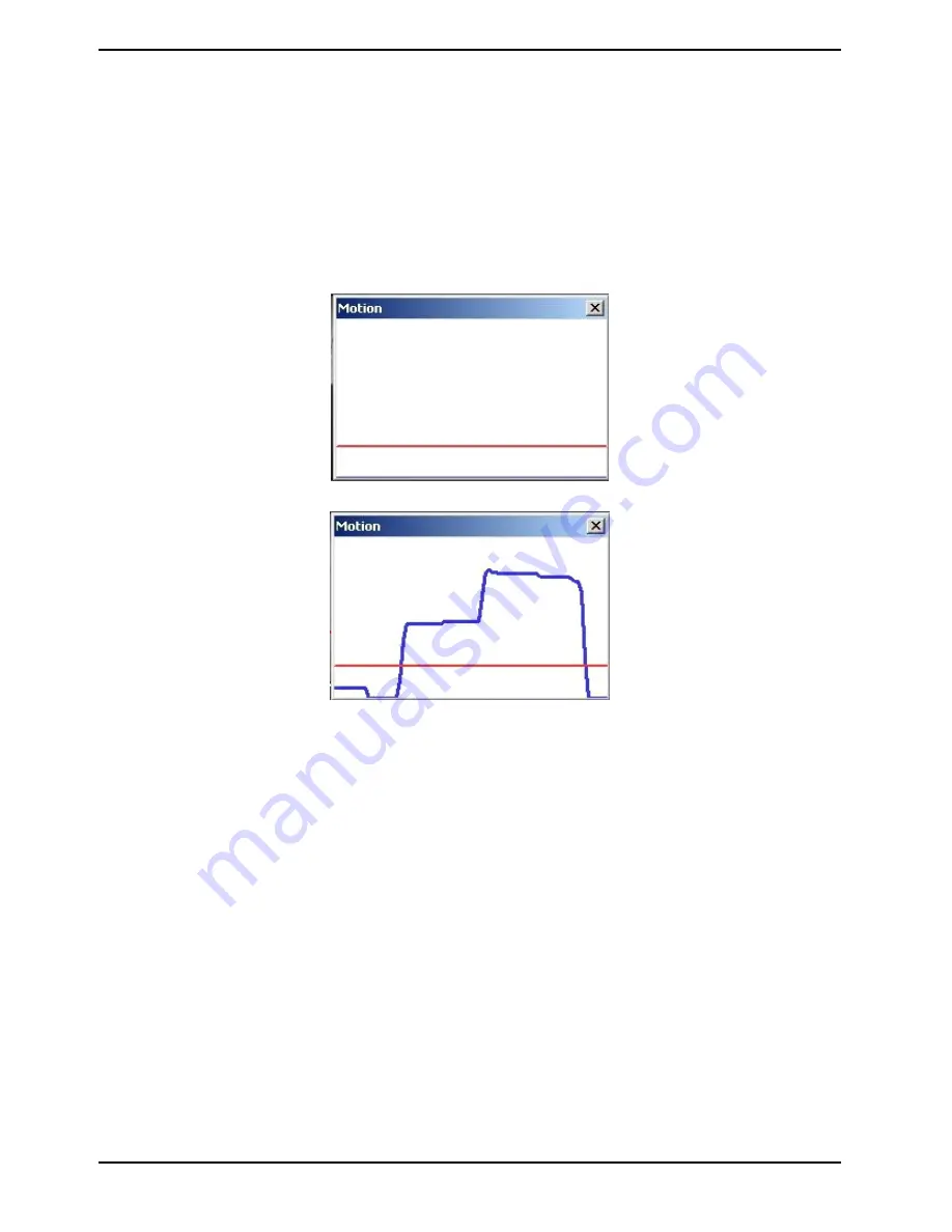
If the Motion Detection function is activated, a pop-up window (Motion) with motion indication will be shown.

When motion is detected, the signals will be displayed in the Motion window as shown below:

The detailed settings of Motion Detection are described as follows:

Motion Detection :
In each set of the Motion Detection Setting, the default setting for the Motion Detection function is <Off>. Enable 
this function by selecting <On>. Users can also activate the function according to the schedule previously set in 
the <Schedule> setting page. Select <By schedule> and click <Please select…> to choose the desired schedule 
from the drop-down menu.

Motion Detection Setting :
Users can adjust various parameters of Motion Detection in this section.


- Sampling pixel interval [1-10]:
The default value is 10, which means the system will take one sampling pixel for every 10 pixel.


- Detection level [1-100]:
The default level is 10. This item is to set the detection level for each sampling pixel; the smaller the value, the 
more sensitive the detection is.

Select <Upload while trigger is active> to record the triggered video until the trigger is turned off.


- Sensitivity level [1-100]: 
The default level is 80, which means if 20% or more sampling pixels are detected as changing, the system will 
detect motion. The bigger the value, the more sensitive the detection is. Meanwhile, when the value is bigger, the 
red horizontal line in the motion indication window will be accordingly lower.

42

English

Содержание GCI-C0745P-1

Страница 1: ...MP Full HD Indoor Motorized Dome IP Camera 18x Zoom ICR WDR GCI K1779P 2 MP Full HD Outdoor Motorized Dome IP Camera 18x Zoom ICR WDR GCI K2795P 2 MP Full HD Outdoor Motorized Dome IP Camera 30x Zoom...

Страница 2: ......

Страница 3: ...Tampering 47 13 Autotracking 51 14 Storage Management on Camera 54 15 Recording on SD Card 57 16 Schedule 57 17 File Location on PC 59 18 View Information 60 19 Factory Default 61 20 Software Version...

Страница 4: ...c shock or damage to the product Do not connect multiple products to one single adapter Exceeding the capacity may cause abnormal heat generation or fire Do not place conductive objects e g screwdrive...

Страница 5: ...urely and firmly A falling unit may cause personal injury If you want to relocate the already installed product be sure to turn the power off and then move or reinstall it 4 1 Preparation for Dome Cam...

Страница 6: ...ction and meets the system requirements as described below Personal Computer 1 Intel Pentium M 2 16 GHz or Intel Core 2 Duo 2 0 GHz 2 2 GB RAM or more Operating System Windows XP Windows VISTA Windows...

Страница 7: ...ction Orange Activity Light flashes for network activity indication 4 5 Alarm Connection The Motordome Camera supports 4 digital alarm inputs and 2 digital alarm outputs Please make sure the alarm con...

Страница 8: ...l appear as shown below Then click on the Find Device button Step 2 The security alert window will pop up Click Unblock to continue Device Search Step 3 Click Find Device again afterwards all IP devic...

Страница 9: ...d to alter the administrator s password due to security concerns Please refer to section 9 2 Security for further details Additionally users can change the IP Camera s network property either to DHCP...

Страница 10: ...ntification Step 2 The Network Setup page will come out Select DHCP and click on the Apply button at the bottom of the page Step 3 Click on OK in the Note of setting the change Wait for one minute to...

Страница 11: ...Install to carry on with the software installation Click on Finish to close the GRUNDIG Viewer window when download is finished For detailed software download procedure please refer to chapter 15 GRUN...

Страница 12: ...ogout and one tab on the right Languages System setting The administrator can set host name system time admin password network related settings etc Further details will be interpreted in chapter 9 Sys...

Страница 13: ...apshot button Press this button and the JPEG snapshots will automatically be saved in the appointed place The default place of saving snapshots is C To change the storage location please refer to sect...

Страница 14: ...he zoom manually or by clicking on the Wide Tele buttons In Full Screen mode users can rotate the mouse wheel to zoom in out on the image Digital zoom is only available when this function is activated...

Страница 15: ...button users can adjust the focus manually via the Near and Far buttons The status will also be displayed above the screen as shown below Multiple Languages Support Multiple languages are supported f...

Страница 16: ...Zoom Zoom In Zoom Out Click on the buttons to zoom in or zoom out Focus Auto Focus Focus Near Focus Far Click on these buttons to adjust the focus near far or automatically Run Preset Cruise Sequence...

Страница 17: ...m tab Each category in the left column will be explained in the following sections NOTE The System configuration page is only accessible by the Administrator 9 1 Host Name System Time Setting Click on...

Страница 18: ...ime display will be synchronised with the PC Manual The Administrator can set the date time and day manually Entry format should be identical with the format shown next to the enter fields Sync with N...

Страница 19: ...user the privileges Camera control Talk and Listen can be assigned I O access This item supports fundamental functions that enable users to view the video when accessing the camera Camera control Thi...

Страница 20: ...es HTTPS allows secure connections between the IP Camera and the web browser using the Secure Socket Layer SSL or the Transport Layer Security TLS which prevent others from snooping on your camera set...

Страница 21: ...under Create self signed certificate and provide the requested information to install a self signed certificate for the IP Camera Please refer to the last part of this section Provide the Certificate...

Страница 22: ...CA Certificate Authority Provide the requested information in the Create Dialog Please refer to the section Provide the Certificate Information for more details When the request is complete the subjec...

Страница 23: ...ate is returned install it by uploading the signed certificate Provide the Certificate Information To create a Self signed HTTPS Certificate or a Certificate Request to CA please enter the information...

Страница 24: ...ation to which the entity identified in Common Name belongs Organisation Unit Enter the name of the organisational unit to which the entity identified in Common Name belongs Common Name Indicate the n...

Страница 25: ...d IP addresses IPv4 Select Allow or Deny from the drop down list and click the Apply button to determine the IP Filter behaviour Add Delete IP Address Input the IP address and click the Add button to...

Страница 26: ...validating itself Upload the certificate for checking the server s identity Client Certificate Private Key Upload the Client Certificate and Private Key for authenticating the IP Camera itself Setting...

Страница 27: ...u with several tabs including Basic QoS SNMP and UPnP Users can choose to connect to the IP Camera through a fixed or dynamic DHCP IP address The IP Camera also provides PPPoE Point to Point Protocol...

Страница 28: ...t Use fixed IP address and move the cursor to the IP address blank as indicated below and insert the new IP address e g 192 168 44 230 then go to Default Gateway explained later and type in the approp...

Страница 29: ...which has the IP address 192 168 0 100 from 80 to 8080 the users must type in in the web browser http 192 168 0 100 8080 instead of http 192 168 0 100 RTSP port The default setting of the RTSP Port is...

Страница 30: ...outers DSCP Settings The DSCP value range is from 0 to 63 The default DSCP value is 0 which means that DSCP is disabled The IP Camera uses the following QoS Classes Video Audio and Management Video DS...

Страница 31: ...lt value is private SNMP v3 This option contains cryptographic security a higher security level which allows users to set the Authentication password and the Encryption password Enable SNMP v3 Check t...

Страница 32: ...es to a management system about important events or status changes Enable Traps Check the box to activate trap reporting Trap address Enter the IP address of the management server Trap community Enter...

Страница 33: ...UPnP component is installed on your computer Please refer to chapter 16 Install UPnP Components for UPnP component installation procedure Enable UPnP port forwarding When UPnP port forwarding is enabl...

Страница 34: ...domain name so that others can connect to it through this name Enable DDNS Check the item to enable DDNS Provider Select one DDNS host from the provider list Host name Enter the registered domain name...

Страница 35: ...e recipients of a message are specified and to whom the message text is transferred The configuration page is shown below Two sets of SMTP can be configured Each set includes the SMTP Server Server Po...

Страница 36: ...ails which include server server port user name password and remote folder into the fields Check the box passive mode to be connected to the FTP server by passively receiving the FTP server s IP addre...

Страница 37: ...ing is finished Please also refer to 9 8 1 Application Alarm Settings Send HTTP notification 9 8 2 Motion Detection for HTTP Notification settings 9 8 Application Alarm Settings The Camera is equipped...

Страница 38: ...e the alarm output signal as high or low for the normal alarm output status according to the current alarm application Triggered Action Multi option The Administrator can specify alarm actions that wi...

Страница 39: ...ges after the alarm input is triggered The post trigger buffer time range is from 1 to 20 frames Check the box Continue image upload to upload the triggered images during a certain time or keep upload...

Страница 40: ...t Upload for __sec and enter the duration in the blank The images of the duration will be uploaded to the FTP when the alarm input is triggered The setting range is from 1 to 9999 seconds Select Uploa...

Страница 41: ...int and stay there for a user defined period of time As for other function modes the camera will keep executing the specified function to stop the performance simply change the camera s status NOTE Th...

Страница 42: ...detected Record Stream to SD Card When you check this item the alarm triggered recording will be stored on your Micro SD SDHC card when tampering is detected The pre trigger buffer recording function...

Страница 43: ...ame imageXX jpg X Sequence Number The file name suffix will end at the number being set For example if the setting is 10 the file name will start from 00 end at 10 and then start all over again Overwr...

Страница 44: ...Detection are described as follows Motion Detection In each set of the Motion Detection Setting the default setting for the Motion Detection function is Off Enable this function by selecting On Users...

Страница 45: ...ill be uploaded to the appointed FTP site The Pre trigger buffer recording function allows users to check what happened to trigger the alarm The pre trigger buffer time range is from 1 to 20 frames On...

Страница 46: ...n Alarm is triggered As soon as an alarm is triggered the notification will be sent to the specified HTTP server For instance if the custom parameter is set as action 1 group 2 and the HTTP server s n...

Страница 47: ...turn the Network Failure Detection on and off Detection Type Here you can set an IP address that should be pinged in order to detect network failure Please also set the interval in minutes for this pi...

Страница 48: ...ction can be implemented See section 9 12 Recording on Camera for further details Send Message by FTP The Administrator can select whether to send an alarm message by FTP when Network Failure is detec...

Страница 49: ...mages will be sent to the appointed e mail address The Pre trigger buffer recording function allows users to check what happened to trigger the alarm The pre trigger buffer time range is from 1 to 20...

Страница 50: ...the Tampering Alarm setting section The default setting is Off Tampering Duration The Minimum Tampering Duration is the time the video analysis will need to determine whether any camera tampering has...

Страница 51: ...g is detected Send Message by E Mail The Administrator can choose to send an alarm message by E Mail when tampering is detected Upload Image by FTP After selecting this item the Administrator can assi...

Страница 52: ...cy as the upload frame rate The setting range is from 1 frame to 15 frames NOTE Make sure SMTP and or FTP configuration has been completed See section 9 5 Mail and 9 6 FTP for further details NOTE Mak...

Страница 53: ...ng The default setting of the Autotracking function is Off Enable this function by selecting On NOTE The setting items will be available after On is selected MAX Limit Setting This setting menu allows...

Страница 54: ...Enable this function by selecting On Sequence line Select a desired sequence line from the drop down menu to set its Autotracking function Preset Select a desired preset point from the drop down menu...

Страница 55: ...users to set the main monitoring area as the Tracking start position and set the duration of time for the camera to track an object NOTE Preset Setting must be Off in order to configure the Guard Tim...

Страница 56: ...o obtain a testing license for 30 days Please contact your system installers or the sales representatives for further information 9 14 Storage Management on Camera Users can store local recordings on...

Страница 57: ...he Storage Management page Device Setting Click on the Format button to format the memory card All data on the memory card will be erased Disk Cleanup Setting Users can enable an automatic recordings...

Страница 58: ...n the Sort button the files in the Recording list will be listed in name and date order NOTE The capital letters A M N R T V appearing in the very beginning of a name denote the sort of the recording...

Страница 59: ...start time hour minute and time period hour minute to activate the recording in certain time frames The setting range for the time period hour is from 0 to 168 Please click on the Save button to confi...

Страница 60: ...minute for activation of the schedule triggered features The setting range for the duration time is from 00 00 to 168 59 Click Delete to delete a chosen time frame Click on Save to confirm the settin...

Страница 61: ...haracters such as letters and numbers NOTE Users with the Windows 7 or Windows 8 operating system on their PC need to follow the following procedure to be able to use the Snapshot and Web Recording fu...

Страница 62: ...on the link to view the system log file The content of this file provides useful information about configuration and connections after system boot up Click on this item to view the entire system s pa...

Страница 63: ...button to recall the factory default settings After 30 seconds the system will restart NOTE The IP address will also be restored to default 192 168 1 1 Partial Restore Click on the Partial Restore bu...

Страница 64: ...he software version page which is shown in the picture below 9 21 Software Upgrade Software upgrade can be carried out on the Software Upgrade page as shown below NOTE Make sure the upgrade software f...

Страница 65: ...upgrade process is finished After the upgrade process is finished the Viewer will return to the Home page Step 4 Close the video browser Step 5 Go to Start on your Windows desktop activate Control Pa...

Страница 66: ...w will pop up as shown below Click Save and specify a desired location for saving the configuration file Upload To copy an existing configuration file to the IP Camera please first click on Browse to...

Страница 67: ...each subtitle can only be 16 characters Users can choose the locations in which the items are to be displayed on the live pane Please note that the items cannot be set to the same location Click Save...

Страница 68: ...OV length to determine the frame structure I frames and P frames in a video stream for saving bandwidth Longer GOV means decreasing the frequency of I frames The setting range for the GOV length is fr...

Страница 69: ...setting of H 264 1 is 4096 kbps and of H 264 2 H 264 3 H 264 4 is 1024 kbps The setting range for H 264 1 is from 64 to 2048 kbps and for H 264 2 H 264 3 H 264 4 it is from 64 to 2048 kbps Click Save...

Страница 70: ...ulticast mode The Video OCX Protocol page is as follows Video OCX protocol setting options include RTP over UDP RTP over RTSP TCP RTSP over HTTP MJPEG over HTTP Select a mode according to your data de...

Страница 71: ...g page is shown below MJPEG H 264 1 H 264 2 H 264 3 H 264 4 Frame Rate The default setting of MJPEG H 264 1 H 264 2 H 264 3 H 264 4 Frame Rate is 25 fps The setting range is from 1 to 25 Click on Save...

Страница 72: ...de the local remote site can only talk to the other site Simplex Listen only In the Listen only Simplex mode the local remote site can only listen to the other site Disable Select this item to turn th...

Страница 73: ...xposure Compensation Digital Zoom etc can also be set here 11 1 Preset In total 256 Preset Points can be programmed for the Motordome Camera Please refer to the instructions below to set a Preset Poin...

Страница 74: ...he menu item Record End to quit Then this Cruise Path will be automatically recorded Cruise Run Select the specified Cruise Path from the drop down list press the Run button and then the camera will s...

Страница 75: ...ion drop down list whether the Auto Pan Path should run in right or left direction Move the camera to another desired position as the end point of the Auto Pan Path Click on the Set button next to the...

Страница 76: ...reset Points Please refer to the instructions below to program a Sequence Line NOTE Before setting this function users must pre define at least two Preset Points Sequence Setting Please press the Edit...

Страница 77: ...ng a Sequence Line in full screen mode please move the cursor onto the live view pane right click and click on full screen to select the full screen view Then users can view the camera navigation in f...

Страница 78: ...y it in the field Type Line Please select a Home action type Preset Point Cruise Line Auto Pan Path Sequence Line from the drop down list Type and select the number of the Preset Point Cruise Line Aut...

Страница 79: ...ask function is enabled Mask Setting Switch The Privacy Mask function can be activated or disabled Click on the button Set to save the setting Transparency The Privacy Mask can be set as transparent i...

Страница 80: ...the parameter of the Shutter Priority P Iris Iris Priority mode for optimised video output according to the operating environment The Maximal Gain can be either turned off or set from 3 to 57 dB Iris...

Страница 81: ...g to the operating environment Light Sources Cloudy Sky Colour Temperature 6 000 to 8 000 K Noon Sun and Clear Sky Colour Temperature 6 500 K Household Lighting Colour Temperature 2 500 to 3 000 K 75...

Страница 82: ...ses through under the Dome Camera with setting Flip to Mechanical M E mode or Digital Flip Image mode NOTE The Flip setting can only be controlled manually If a Preset Position or a point for another...

Страница 83: ...r s sensitivity to light will be enhanced Without the IR cut filter the image sensor can now also process IR light Auto In Auto mode the internal circuit will automatically decide to remove the IR cut...

Страница 84: ...e Camera such as NE 050 00 NE indicates the shooting position of the Dome Camera N North E East 050 indicates the pan degree 00 indicates the tilt degree Click on the Set button to save the setting Se...

Страница 85: ...e network via the Video Server into one system Offering powerful functionalities via intuitive interface it is a centralised monitoring solution for your video surveillance equipments The GRUNDIG CMS...

Страница 86: ...Internet security level to default or change ActiveX controls and plug in settings Internet Security Level Default Step 1 Start the Internet Explorer Step 2 Select Tools from the main menu of the brow...

Страница 87: ...e the browser window and open a new one later when accessing the IP Camera ActiveX Controls and Plug in Settings Step 1 3 Please refer to the previous section above Step 4 Down the page click on Custo...

Страница 88: ...tiveX controls 4 Binary and script behaviors 5 Display video and animation on a webpage that does not use external media player 6 Download signed ActiveX controls 7 Download unsigned ActiveX controls...

Страница 89: ...rocedure of the GRUNDIG Viewer software download is specified as follows Step 1 In the GRUNDIG Viewer installation page click Next to start the installation Step 2 Setup starts Please wait for a while...

Страница 90: ...k on Finish to close the GRUNDIG Viewer installation page Then the IP Camera s Home page will be displayed as follows NOTE Please note that the function buttons may vary depending on the camera model...

Страница 91: ...mponents The procedure is for Windows XP for other systems please refer to the corresponding manuals Step 1 Go to Start click on Control Panel and then double click on Add or Remove Programs Step 2 Cl...

Страница 92: ...nents list in the Windows Components Wizard window and then click on Details Step 4 Select UPnP User Interface in the Networking Services subcomponents list and then click on OK Step 5 Click on Next i...

Страница 93: ...he GRUNDIG Viewer Click on Control Panel and then click on Add or Remove Programs In the Currently installed programs list select GRUNDIG Viewer and click the button Remove to uninstall the existing G...

Страница 94: ...ick on the Tools tab and select the option Internet Options STEP 2 Click on Delete in the first pop up window Then tap Delete Files in the Temporary Internet files section in the next pop up window 92...

Страница 95: ...264 H 264 or H 264 H 264 H 264 MJPEG Video Resolution 1920 x 1080p SXGA 1280 x 720p XGA SVGA 4CIF VGA CIF Network Protocol IPv4 v6 TCP IP UDP RTP RTSP HTTP HTTPS DHCP PPPoE UPnP SMTP ICMP IGMP SNMP I...

Страница 96: ...ution 25fps 2MP 50fps 1 3MP etc Streaming Method Unicast Multicast Audio Communication Bi directional Access protection By log in and Password IP filter IEEE802 1x Number of Clients Up to 20 user 1 x...

Страница 97: ...olution Full HD 1080p SXGA HD 720p XGA SVGA D1 VGA CIF QCIF Frame Rate Max Resolution 25fps 2MP 50fps 1 3MP etc Streaming Method Unicast Multicast Audio Compression G 726 G 711 Audio Communication Bi...

Страница 98: ...Audio Compression G 726 ADPCM G 711 Protection Rating IP66 IK10 Operating Temperature 40 C 50 C 60 W Power Consumption 2 6 kg Weight 190 X 303 mm Dimensions wxhxd Dimensions 96 English...

Страница 99: ...products meet the standards in the following relevant provisions EC EMC Directive 2004 108 EC Applied harmonised standards and technical specifications EN 55022 2010 Class A EN 61000 3 2 2006 A1 2009...

Отзывы: