5
4. Installation
4.1 Location
The booster set should be placed in a well-ventilated room to en-
sure adequate cooling of the pump motors. It should be placed
with a 1 metre clearance in front and on the two sides.
Use a fork-lift truck to move the booster set.
4.2 Foundation
The booster set does not require a special foundation, but it should
be positioned on a plane and solid surface, e.g. a concrete floor.
4.3 Pipework
Arrows on the pump bases show the flow direction of the water
through the pumps.
The pipes connected to the booster set must be of adequate size.
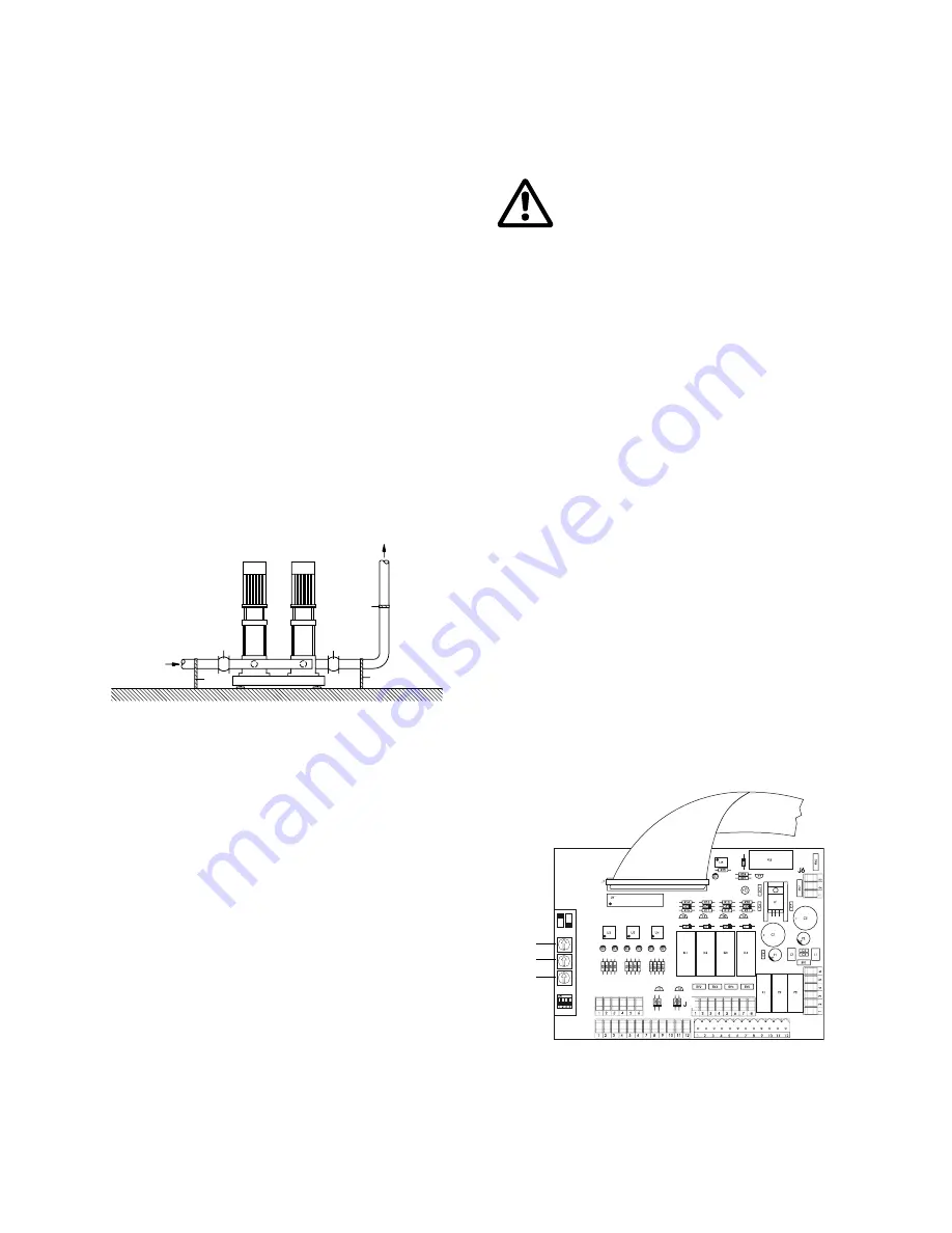
To avoid resonance, expansion joints should be fitted in the suc-
tion and discharge pipes, see fig. 4.
The pipes are connected to the manifolds of the booster set. Ei-
ther end can be used. Apply sealing compound to the unused end
of the manifold and fit a screw cap. For manifolds with flanges, a
blind flange with gasket is fitted.
The booster set should be tightened up before start-up.
The pipes must be fastened to parts of the building to ensure that
they cannot move or be twisted.
Fig.
4
1. Expansion joint.
2. Pipe hanger.
Expansion joints, pipe hangers and vibration dampers shown in
fig. 4 are not included in the standard booster set.
4.4 Dry-running protection
It is possible to install a pressure switch on the suction side of the
booster set to monitor the inlet pressure and to prevent the
booster set from running dry (a level switch can be used if the
suction side is connected to an open tank).
The booster set should not be started until a dry-running protec-
tion has been installed. When the inlet pressure/level drops below
the set value, the pumps are cut out. When the correct pressure/
level value is restored, the pumps can be reset to operation auto-
matically or manually.
4.5 Priming
Do not start the pumps until they have been filled with water. See
installation and operating instructions for CR pumps.
4.6 Electrical connection
The electrical connection should be carried out by an authorized
electrician in accordance with local regulations.
The wiring diagram and motor labels show required values for the
electricity supply.
No additional motor protection is required as the control box in-
corporates motor protection.
5. Settings
5.1 Timers
The three timers incorporated in the controller CS 1000 can be
used to optimize the operation of the booster set. The timers are
to be adjusted individually.
Start-up delay TR 1 (0-5 secs.)
Defined as:
The minimum time between starts of individual
pumps.
Prevents:
simultaneous start of all pumps in case of:
- momentary power failure,
- peak of water demand,
- automatic resetting of dry-running.
negative pressure in suction manifold.
overload of power mains.
water hammer.
Stop delay TR 2 (0-5 secs.)
Defined as:
The minimum time between stops of individual
pumps.
Prevents:
simultaneous stop of all pumps in case of:
- rapid fall of water demand.
water hammer.
Reduces:
number of starts and stops per hour.
After-run delay TR 3 (0-5 secs.)
Defined as:
The time that pumps are kept in operation after
the cut-out pressure is reached.
Keeps:
pumps in operation when the cut-out pressure is
reached.
Reduces:
number of starts and stops per hour.
Fig.
5
T
M
00
77
48
19
96
2
2
1
1
2
Before making any connections in pumps, terminal
boxes or control box, the electricity supply must be
switched off.
T
M
00
97
42
03
97
J2
J4
TR 1
TR 2
TR 3


