background image

U0627512 / 00CNO0192-E  

08.04.2021

For professional. 

To be retained by the user for future reference

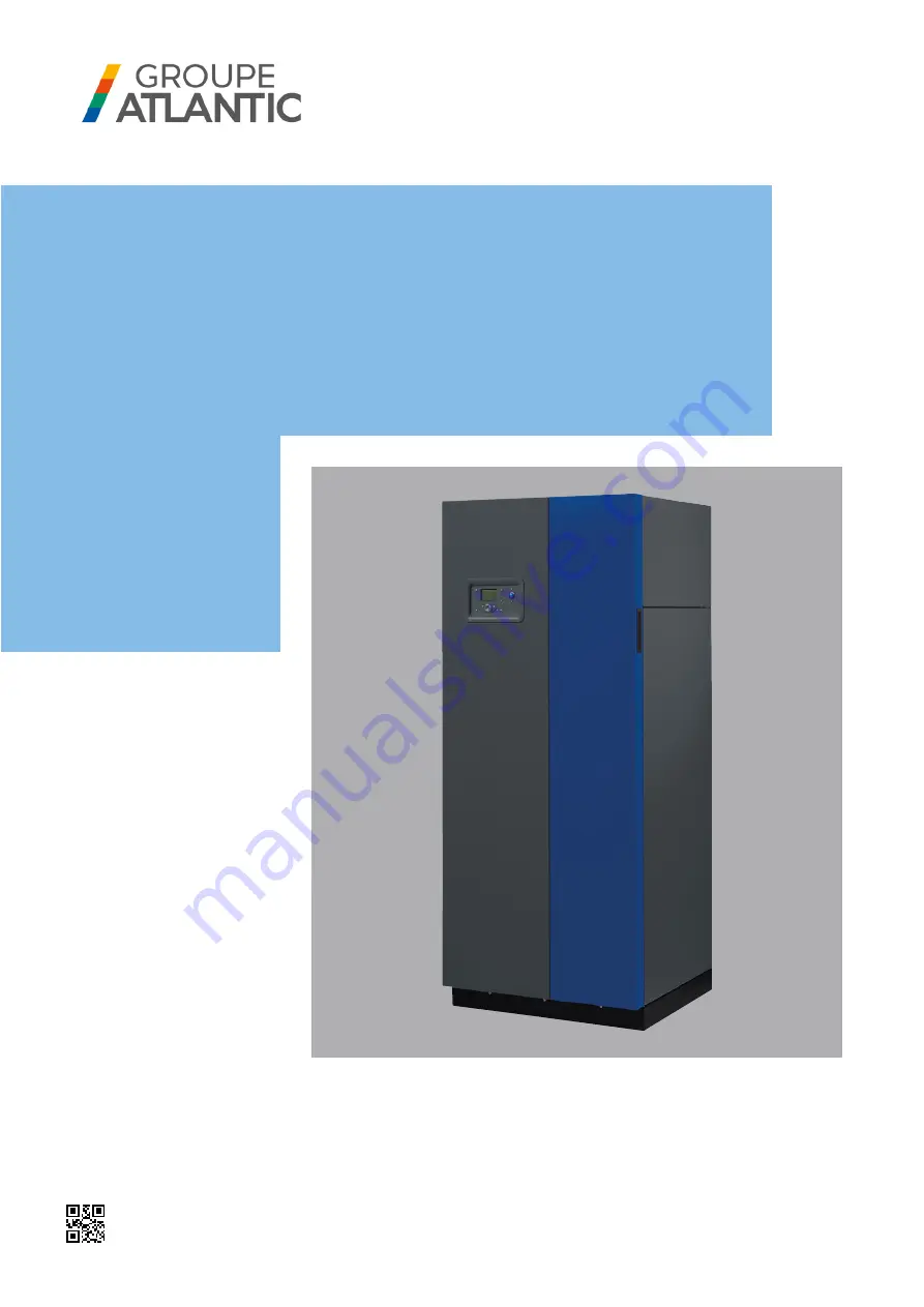
Gas condensing 

boiler 40, 50, 60, 

80 or 100 kW with 

modulating burner 

for natural gas and 

propane gas

CONDENSINOX

INSTALLATION, USE AND MAINTENANCE INSTRUCTIONS

Содержание CONDENSINOX 100

Страница 1: ... 2021 For professional To be retained by the user for future reference Gas condensing boiler 40 50 60 80 or 100 kW with modulating burner for natural gas and propane gas CONDENSINOX INSTALLATION USE AND MAINTENANCE INSTRUCTIONS ...

Страница 2: ...2 116 00CNO0192 E U0627512 CONDENSINOX Installation Use and Maintenance ...

Страница 3: ...d 1013 mbar 13 3 3 Conditions of use 14 3 4 Electrical connection 14 4 INSTALLATION 15 4 1 Boiler location 15 4 2 Removing refitting the front panel 16 4 3 Removing refitting the upper cover 16 4 4 Exhaust connection 17 4 5 Hydraulic connection 25 4 6 Connecting the gas supply 27 4 7 Changing the gas 27 4 8 Electrical connection 31 5 COMMISSIONING 36 5 1 Checks before commissioning 36 5 2 Commissi...

Страница 4: ...nce 9 HYDRAULIC DIAGRAMS AND CONFIGURATIONS 42 9 1 Selection diagrams 42 9 2 Symbols used in the diagrams 44 9 3 List of diagrams 44 9 4 Specific configurations when connecting to 0 10V outputs Ux 88 10 SPARE PARTS LIST 92 11 CUSTOMER PARAMETERS TABLE 100 12 ANNEX A 115 ...

Страница 5: ... to other objects DANGER Failure to comply with these instructions may cause injury and serious material damage DANGER Failure to comply with these instructions may cause electrocution 1 3 Staff qualification for installation adjustment use and maintenance The appliance must be installed configured and maintained by a qualified approved professional in accordance with the local and national regula...

Страница 6: ...ation new or renovation the water system pipes must be thoroughly cleaned The purpose of this initial cleaning is to eliminate germs and residue that can cause deposits to form In new installations in particular any residues of grease oxidised metal or copper micro deposits must be removed In renovated installations cleaning should focus on removing sludge and the products of corrosion formed when...

Страница 7: ...n the installation the equipment must be checked frequently to ensure it is not discharging chloride rich water into the system the chloride concentration must always remain below 50 mg litre To prevent the build up of calcium deposits such as on exchange surfaces the unit should be brought into service slowly starting by operating at a low power with high primary water flow If the water in the sy...

Страница 8: ...here is a chance that oxygen could enter the unit you must take additional precautions Adding an oxygen scavenger e g sodium sulphite is highly recommended We recommend directing any water treatment questions to specialists who can provide The appropriate treatment based on the characteristics of the unit A monitoring agreement with a guarantee as to the results In the case of an installation in w...

Страница 9: ...cannot be met you can set up a plate exchanger to separate the primary system from the secondary system which protects the boiler from undesirable effects 1 5 6 Setting up a filtration system A filtration system on the boiler return circuit is recommended in order to remove suspended particles from the unit filter dirt separator etc ...

Страница 10: ...sation boilers with a power of less than or equal to 70 kW is available in appendix A Eco design 2009 125 EC from 26 09 2015 In application of the directive and according to the requirements of the EU regulation No 813 2013 of 02 August 2013 the technical parameters of condensation boilers with a power of less than or equal to 400 kW are available in appendix A 2 2 Regulatory installation conditio...

Страница 11: ...43 C83 I2H I2H CONDENSINOX 50 kW B23 B23 P I2H CONDENSINOX 80 100 kW B23 B23 P II2H3P I2H C13 C33 C53 C43 C83 I2H I2H 2 4 Gas supply pressures INFORMATION The pressures given below should be measured at the input to the gas valve H G20 natural gas L G25 natural gas G31 propane only with B23 and B23P Nominal pressure mbar 20 25 37 Minimum pressure mbar 17 20 25 Maximum pressure mbar 25 30 45 ...

Страница 12: ...n Cold return Condensate discharge MODEL A B C D E F G H I J Ø K L M Ø N O P mm mm mm mm mm mm mm mm mm mm mm mm mm 40 60 1494 595 708 1449 58 100 336 400 406 76 1 1 4 1354 209 G1 2 114 670 70 80 100 1707 695 813 1626 102 110 336 400 550 85 1 1 4 1529 130 G3 4 114 773 P gas connection removed see paragraph 4 6 Gas connection U0627216 C 20 mini 40 maxi B A P E O G H I Ø N Ø K M F J Ø K Ø K Ø 25 D L...

Страница 13: ...19 4 0 28 3 5 9 28 3 5 9 38 5 7 9 46 5 9 6 Exhaust mass flow rate at Qn Qmin 50 30 C g s 17 8 3 5 21 5 5 25 3 5 5 35 9 7 3 43 5 8 9 Exhaust temperature at Qn Qmin 80 60 C C 74 56 67 54 85 55 76 57 82 57 Exhaust temperature at Qn Qmin 50 30 C C 48 29 43 34 58 30 56 30 56 30 Exhaust circuit pressure loss at Qn Pa 135 130 162 145 140 Exhaust outlet diameter mm 80 80 80 100 100 Maximum allowable nozzl...

Страница 14: ...5 2 6 8 8 4 Water capacity L 94 88 88 136 130 Weight without water kg 134 140 140 215 225 Room temperature min max C 5 45 Room relative humidity 5 to 95 Level of protection IP20 Maximum installation altitude m 2000 3 4 Electrical connection MODEL 40 50 60 80 100 Electrical power supply V 230 V AC 10 15 50Hz Electrical power consumption at Qn excluding accessories W 120 142 160 210 280 Electrical p...

Страница 15: ...ling Sufficient clearances must be provided to permit easy maintenance operations on the boilers The minimum values in mm are indicated in figure 2 and the table below A mm B mm C mm H mm MODEL 40 50 60 200 150 200 1750 80 100 500 365 500 1980 figure 2 Clearance around the boiler Zone that must remain clear to allow opening of the combustion chamber door note the combustion chamber door can only b...

Страница 16: ... as a reference surface To adjust the level screw or unscrew the 4 adjustable feet as required using a 13 mm wrench 4 2 Removing refitting the front panel 1 Tilt the front panel forward use the handles located on the door thickness Disconnect the earth wire on the top left of the boiler 2 Lift the front panel to remove it 4 3 Removing refitting the upper cover Pull the upper cover forward Lift the...

Страница 17: ...ENSINOX boiler to a B23 chimney duct This kit is suitable for Ø 160 exterior ducts ATTENTION Under no circumstances is use of these mandatory accessories a substitute for checking the dimensioning of the chimney ducts given a combustion gas pressure at the boiler outlet equal to 0 Pa The exhaust extraction ducts must be made in a material resistant to the condensate that can form when the boiler i...

Страница 18: ... the installation room gas evacuation through the roof via a pressurised duct ATTENTION The use of the Chimney Adaptor accessory is mandatory to connect a CONDENSINOX boiler to a B23P chimney duct The table below represents the accessories available for each boiler type ATTENTION Ensure that the room where the boiler is installed has high and low ventilation outlets in accordance with the regulati...

Страница 19: ...y code 040940 has a 125 diameter outlet that cannot be recut Height A in mm Ø duct CONDENSINOX 40 50 60 80 100 Ø 80 1605 min 1910 max Ø 110 1635 1795 Ø 125 1690 1910 Ø 160 1925 A purge tee is not necessary because condensate recovery is incorporated in the boiler Use a minimum slope of 3 towards the boiler in the horizontal parts To ease fitting coat the joints with liquid soap or an appropriate g...

Страница 20: ...e dimensioned by using the parameters set out in the table in chapter 3 2 Depending on the actual configuration of the duct a calculation is required to check that the pressures at the boiler outlet do not exceed the maximum allowable values in this table Values corresponding to the 50 30 C regime are to be used for this calculation The installation must be done so that if one of the boilers is st...

Страница 21: ...e duct diameters and the maximum straight lengths The approved ducts are Ubbink Rolux Concentric Condensation ducts CONDENSINOX 40 60 80 100 C13 type horizontal air vent C13 terminal Code 040946 Code 040987 Ø duct Concentric 80 125 Concentric 100 150 A min mm 1552 1750 Lmax 12 m 15 m 10 m 10 m C33 type vertical air vent Black C33 terminal Code 040947 Code 040988 Ochre C33 terminal Code 040948 Ø du...

Страница 22: ...rethane foam to allow for removal if necessary To ease fitting coat the joints with liquid soap or an appropriate grease 4 4 5 Connection to a C53 vent G20 and G25 only C53 type connection Air intake and gas evacuation via 2 separate ducts IMPORTANT The use of the Black vertical separate air vent or Ochre vertical separateairvent accessoryismandatorytoconnectaCONDENSINOX boiler with a separate C53...

Страница 23: ...ing terminal 0 2 4 6 8 10 12 14 16 18 20 0 2 4 6 8 10 12 14 16 18 20 L conduit air m L1 conduit fumées m 0 5 10 15 20 25 0 2 4 6 8 10 12 14 16 18 20 L conduit air m L1 conduit fumées m figure 9 Max length of C53 type ducts CONDENSINOX 40 60 figure 10 Max length of C53 type ducts CONDENSINOX 80 100 L1 exhaust duct m L air duct m CONDENSINOX 40 CONDENSINOX 60 L1 exhaust duct m L air duct m L1 exhaus...

Страница 24: ...grease 4 4 6 C43 or C83 collective air vent connection IMPORTANT For these connection types consult us 4 4 6 1 Type C43 The boilers are connected to a common duct comprising two ducts connected to a terminal that provides extraction of combustion products and combustion air intake through orifices that are concentric or sufficiently close to operate in similar wind conditions 4 4 6 2 Type C83 The ...

Страница 25: ...fully to minimise pressure losses and so avoid overspecified circulating pumps In some cases the diameter of the connection pipes will be greater than the diameter of the boiler tappings The diameter can then usefully be increased after the union connectors the stop valves and or the hydraulic balancing valves The diagram below allows approximate sizing of these pipes Note that this does not take ...

Страница 26: ... are fitted with 2 returns and an optimised internal water circuit allowing effective separation of high temperature returns coming from DHW preparation circuits ATU radiators from low temperature circuits underfloor heating circuits low temperature radiator circuits This circuit separation encourages the condensation of exhaust in the lower part of the exchanger throughout the year and so conside...

Страница 27: ...g gas to the installation ensure that the different connections are correctly made and gas tight In particular check the presence of a removable connector between the isolating valve and the boiler gas supply tapping The value read at the gas valve input upstream pressure tapping must be between 17 and 25 mbar when operating at the maximum pressure group H and type G20 natural gas ATTENTION The ga...

Страница 28: ...0 G25 G31 Supply pressure mbar 20 25 37 4 7 1 Changing from G20 to G25 Before starting the burner on the gas valve preset the gas flow rate using the gas flow rate adjustment screw R1 to the appropriate value given in the table below Start the burner at maximum power Using a combustion analyser measure the CO2 ratio in the exhaust gases on the concentric adapter remove the plug from the lower open...

Страница 29: ...8 9 9 1 8 4 8 6 60 GB WND 055 D01 S20 G20 8 9 9 1 8 4 8 6 G25 set up for G20 6 9 7 1 6 4 6 6 G25 Unscrew R1 direction 1 5 2 turns 8 6 8 8 8 1 8 3 G31 Screw R1 direction 2 2 25 turns screw R2 direction 1 turn 11 2 11 4 11 0 11 2 80 GB WND 057 D01 S20 G20 8 7 8 9 8 4 8 6 G25 set up for G20 6 8 7 0 6 7 6 9 G25 Unscrew R1 direction 2 turns 8 6 8 8 8 0 8 4 G31 Screw R1 direction 2 turns screw R2 direct...

Страница 30: ... Before starting the burner on the gas valve preset the gas flow rate using the R1 gas flow rate adjustment screw to the appropriate value given in the table above Start the burner at maximum power Using a combustion analyser measure the CO2 ratio in the exhaust gases on the concentric adapter remove the plug from the lower opening and insert the CO2 measurement sensor into the centre of the flow ...

Страница 31: ...rcuit breaker upstream of the boiler distance between contacts 3 5 mm minimum Fitting the electrical installation with a 30 mA differential protective device is strongly advised See the installation and use manual for the NAVISTEM B3000 boiler controller for information about the electrical connections of the control panel characteristics of the power supply cable section and terminal connections ...

Страница 32: ...ump control The lower tray is dedicated to signal connections sensors communication bus etc Use the cable clamps not shown at the entrance to the cable trays to block the cables mechanically For the connection of the general power supply comply with the wiring diagram in particular the phase neutral and earth polarities figure 17 Electrical cable duct High current tray power supply Low current tra...

Страница 33: ...dule optional accessory To install the OCI345 module refer to the manual supplied with the accessory reference 059752 4 8 6 Fuses The CONDENSINOX boiler is equipped with 4 fuses located on the boiler controller see the label on the protective cover for their locations and characteristics 3 spare fuses are also provided on the boiler controller 4 8 3 Connection to the boiler controller terminal blo...

Страница 34: ... 3 4 5 6 7 8 9 1 2 3 4 5 6 7 8 9 1 2 3 4 5 6 7 8 1 2 1 2 3 4 5 6 7 8 1 2 1 2 1 2 1 2 3 1 2 1 2 1 2 1 2 1 2 3 X30 X50 AVS75 x3 U0570440 A 00CET0072 A A1 A2 L2A L2B N1A N1B QAA 75 x 3 G CL CL B2 B7 0 10V L N QAC 34 QAZ 36 QAD 36 QAD 36 230 V M DB MB OCI 345 HMI AVS75 OCI345 X11 HMI 0 10V 0 10V NAVISTEM B3000 _ U0570440 B 00CET0072 B ...

Страница 35: ...ual should you require further information on the characteristics of borniers Cascade flow sensor Room sensor Cascade return sensor Boiler flow sensor DHW sensor Boiler return sensor External sensor Flue gas sensor Input prog client 0 10V Alarm relay Output prog client 0 10V Modulating pump Input prog client contact ...

Страница 36: ...according to the type of chimney see section 4 2 ATTENTION If there is a B23 B23P chimney connection it is ESSENTIAL to use the Chimney adaptor accessory consisting of an air intake grille a filter sheet an adaptor duct 5 2 Commissioning Before packing all boilers are subjected to a factory test using group H type G20 natural gas during which all the settings are done For commissioning perform the...

Страница 37: ...pply Check that the gas pipe diameter is correctly sized It is necessary to stop all the boilers together abruptly using the boiler room main circuit breaker to check that the gas pressure regulator safety device is not triggered If this is triggered the gas pipe is undersized After this operation re engage the circuit breaker The boilers should start automatically if not consult the supplier of t...

Страница 38: ...sually If necessary remove the turbulators and clean the tubes mechanically 7 4 Ignition ionisation electrodes Check the ignition electrodes air gap distance If necessary replace the electrode unit Condensate removal siphon Clean the removal siphon and check that the condensates flow correctly replace the water after checking Check the correct condition and connection of the pressure transfer pipe...

Страница 39: ... the turbulators for the exchanger tubes Brush the exchanger tubes with the tube brush provided Brush the combustion chamber with a brush suitable for stainless steel Suck out the deposits in the combustion chamber Suck out the deposits that have fallen into the smoke box through the chimney sweeping hatch at the front and below the body hatch fixed by 2 M8 H nuts Reclose and fix the chimney clean...

Страница 40: ...s sealed and check the combustion health CO2 level compliant with the values in the table in section 4 5 and CO 10 ppm Refit the top cover 7 4 Checking the ignition and ionisation electrodes The ignition electrode for CONDENSINOX boilers is adjusted in the factory to obtain optimum boiler starting Check the condition and geometry of the arc electrode Check the electrode burner distance figure 21 E...

Страница 41: ...oduct can prevent damage to the environment and health risks a For the disposal of the product and the component parts the services of an accredited waste disposal company should be used b For more information on waste disposal management contact the Local Authority responsible for waste management or the point of sales where the product was purchased ...

Страница 42: ...ting via LPB bus Secondary networks via existing communicating regulation CX3 1 Secondary networks via existing communicating regulation CX3 1 1 direct heating network CX4 1 Networks 1 2 or 3 regulated by V3V with accumulated DHW CX1 1 No management of secondary networks Single boiler direct circuit 1 2 or 3 network s regulated Accumulated DHW Management of secondary networks ...

Страница 43: ...W Cascade management by ATLANTIC Secondary network management by external regulation with LMU Mixed Boiler cascade 2 networks regulated with accumulated DHW CX15 1 2 or 3 networks regulated by V3V 1 direct network with accumulated DHW CX13 1 Management of secondary networks direct circuit 1 2 or 3 network s regulated Accumulated DHW CX14 1 Secondary networks regula ted by external non commu nicati...

Страница 44: ...SINGLE BOILER 49 Regulated networks and existing DHW production external regulation communicating via LPB bus or 0 10V signal 49 CX3 3 or more regulated networks with or without DHW production 52 CX4 Regulated networks and DHW regulated by external regulator communicating via LPB bus or 0 10V signal 58 CX10 3 networks regulated by 3 way valves 1 direct circuit with DHW production 64 CX11 Heating c...

Страница 45: ...Q2 Single boiler 1 regulated heating circuit Diagram CX1 page 1 4 A HYDRAULIC DIAGRAM figure 22 Diagram CX1 B REGULATION ACCESSORY NECESSARY Quantity Appliance reference Order no External sensor kit 1 QAC 34 059260 Bypass required in case of underfloor heating network ...

Страница 46: ...s Start up the boiler alone Make the following adjustments Line No Value Menu Time and date Set the time Hour minute 1 HH MM Set the date Day month 2 DD MM Set the year Year 3 YYYY Menu Configuration Start heating circuit 1 Heating circuit 1 5710 On Define pump Q2 output Relay QX2 output 5891 Pump HC1 Q2 Menu Heating circuit 1 Adjust the comfort setpoint Comfort temperature setpoint 710 Set the cu...

Страница 47: ...heck the sensor values Outdoor sensor B9 B9 exterior T 7730 in C F OPTIMISING THE SETTINGS Menu Heating circuit 1 Adjust the low setpoint Low setpoint temperature 712 Menu HC1 timer program Preselection Preselection 500 Adjust the programmed times On off phases 501 506 Menu HC1 holidays Preselection Preselection 641 Adjust the programmed times On off phases 642 643 Switch the heating program to au...

Страница 48: ...boiler fault This maintenance message can occur after the 3 following counters reach set values Time since last maintenance or commissioning set parameter 7044 to 12 months Hours of burner operation parameter 7040 Number of start ups parameter 7042 The last 2 parameters depend on the boiler room s hydraulic installation It is advisable to use at least parameter 7044 for annual maintenance ...

Страница 49: ...ntity Appliance reference Order no Communication kit for LPB bus 1 OCI 345 059752 Single boiler Regulated networks and existing DHW production external regulation communicating via LPB bus or 0 10V signal Diagram CX3 page 1 3 A HYDRAULIC DIAGRAM EXTERNAL COMMUNICATING REGULATOR LPB bus to OCI345 or 0 10 V signal to B3000 ...

Страница 50: ...START UP PROCEDURE Fit and connect the accessories Start up the boiler alone Make the following adjustments Line No Value Menu Time and date Set the time Hour minute 1 HH MM Set the date Day month 2 DD MM Set the year Year 3 YYYY For a request via 0 10V input Menu Configuration Configure input H1 H1 input function 5950 Request consum circ 1 10V H1 voltage value 1 5953 0 0 H1 function value 5954 0 ...

Страница 51: ... SETTINGS Maintenance optimisation It is possible to generate a maintenance message that does not cause a boiler fault This maintenance message can occur after the 3 following counters reach set values Time since last maintenance or commissioning set parameter 7044 to 12 months Hours of burner operation parameter 7040 Number of start ups parameter 7042 The last 2 parameters depend on the boiler ro...

Страница 52: ... Extension module kit supplied with a QAD 36 network sensor 3 AVS 75 059751 External sensor kit 1 QAC 34 059260 Room sensor kit option 3 QAA 75 040954 DHW sensor kit 1 QAZ 36 059261 For an installation with more than 3 circuits an RVS63 and an OCI345 communication module must be added Single boiler 3 or more regulated networks with or without DHW production Diagram CX4 page 1 6 A HYDRAULIC DIAGRAM...

Страница 53: ...r heating and or DHW circuit is connected refer to 9 4 for the specific configuration C CUSTOMER ELECTRICAL CONNECTION L2 N L3 N L3 L1 N QX2 QX3 QX1 G CL CL G CL CL 230 VAC 50 Hz power supply External sensor B9 Alarm relay DHW sensor B3 Room sensor QAA 75 heating circuit no 1 Room sensor QAA 75 heating circuit no 2 Room sensor QAA 75 heating circuit no 3 Diagram CX4 page 2 6 DHW pump Q3 ...

Страница 54: ...eating circuit 3 mixing valve Y11 Y12 Heating circuit 1 circulating pump Q2 Heating circuit 2 circulating pump Q6 Heating circuit 3 circulating pump Q20 D SPECIFIC START UP PROCEDURE Fit and connect the accessories Start up the boiler alone Make the following adjustments Line No Value Menu Time and date Set the time Hour minute 1 HH MM Set the date Day month 2 DD MM Set the year Year 3 YYYY Menu C...

Страница 55: ...ircuit Adjust the comfort setpoint Comfort temperature setpoint 710 1010 1310 Set the curve slope Heating curve slope 720 1020 1320 Set the heating program to permanent comfort E ELECTRICAL AND HYDRAULIC VALIDATION Menu Input output test Check the outputs Alarm relay Relay test 7700 Relay QX1 output All extension module relays Relay test 7700 Relay output QX2 module Reset the outputs Relay test 77...

Страница 56: ...election 641 651 661 Adjust the programmed times On off phases 642 643 652 653 662 663 Switch the heating program to automatic AUTO Optimisation de l ECS Line No Value Menu Domestic Hot Water Adjust the low setpoint Low setpoint 1612 Set the DHW release program DHW release 1620 Timer prog 4 DHW Menu Timer program 4 DHW Preselection Preselection 560 Diagram CX4 page 5 6 Configuration menu Activate ...

Страница 57: ...et values Time since last maintenance or commissioning set parameter 7044 to 12 months Hours of burner operation parameter 7040 Number of start ups parameter 7042 The last 2 parameters depend on the boiler room s hydraulic installation It is advisable to use at least parameter 7044 for annual maintenance G ROOM SENSOR CONFIGURATION Link each sensor to a heating circuit User interface menu for each...

Страница 58: ... regulator communicating via LPB bus or 0 10V signal Diagram CX10 page 1 6 A HYDRAULIC DIAGRAM B REGULATION ACCESSORIES NECESSARY Quantity Appliance reference Order no Communication kit 2 OCI 345 059752 Network sensor kit 1 QAD 36 059592 figure 25 Diagram CX10 EXTERNAL COMMUNICATING REGULATOR LPB bus to OCI345 or 0 10 V signal to B3000 ...

Страница 59: ...LPB Bus C CUSTOMER ELECTRICAL CONNECTION Boiler no 1 L2 N L3 N L3 L1 N QX2 QX3 QX1 230 VAC 50 Hz power supply Alarm relay 0 to 10V analogue input Isolation valve Q1 1 Cascade flow sensor B10 INFORMATION If the isolation valve is not equipped with an automatic reset connect the isolation valve Q1 1 close contact to L3 Boiler no 2 INFORMATION If the isolation valve is not equipped with an automatic ...

Страница 60: ...ster Line No Value Menu Time and date Set the time Hour minute 1 HH MM Set the date Day month 2 DD MM Set the year Year 3 YYYY Menu Configuration Configure the isolation valve Q1 1 Relay QX3 output 5892 Boiler pump Q1 Configure the cascade flow sensor B10 Sensor input BX2 5931 Common flow sensor B10 For a request via 0 10V input Configure input H1 H1 input function 5950 Request consum circ 1 10V H...

Страница 61: ...nu LPB network Configure the boiler as slave in the cascade Appliance address 6600 2 or above for the other slaves Segment address 6601 0 Bus supply function 6604 Automatic Clock operation 6640 Slave without adjustment Connect the bus between the boilers take care to respect the polarity Switch the slave boiler s off and on again If communication is established properly the clock is updated correc...

Страница 62: ...Menu Input output test H1 voltage H1 voltage signal 7840 To be confirmed against the voltage sent by the boiler room controller For a request via LPB If the boiler room regulator is configured as a slave clock it must retrieve the date and time Menu Input output test Check the outputs Alarm relay Relay test 7700 Relay QX1 output Isolation valve Q1 1 Relay test 7700 Relay QX3 output Reset the outpu...

Страница 63: ... the Cascade menu See the NAVISTEM B3000 boiler controller manual for more details Diagram CX10 page 6 6 Maintenance optimisation It is possible to generate a maintenance message that does not cause a boiler fault This maintenance message can occur after the 3 following counters reach set values Time since last maintenance or commissioning set parameter 7044 to 12 months Hours of burner operation ...

Страница 64: ...ction Diagram CX11 page 1 10 A HYDRAULIC DIAGRAM B REGULATION ACCESSORIES NECESSARY Quantity Appliance reference Order no Extension module kit supplied with a QAD 36 network sensor 3 AVS 75 059751 Communication kit 2 3 OCI 345 059752 Network sensor kit 1 QAD 36 059592 External sensor kit 1 QAC 34 059260 DHW sensor kit 1 QAZ 36 059261 figure 26 Diagram CX11 ...

Страница 65: ...n automatic reset connect the isolation valve Q1 1 close contact to L3 L2 N L3 N L3 L1 N QX2 QX3 QX1 230 VAC 50 Hz power supply External sensor B9 DHW sensor B3 Cascade flow sensor B10 Alarm relay Isolation valve Q1 1 Diagram CX11 page 2 10 DHW pump Q3 AVS75 QX21 N QX22 N QX23 BX21 Gnd BX22 Gnd H2 Gnd Module 1 Heating circuit 1 circulating pump Q2 AVS75 QX21 N QX22 N QX23 BX21 Gnd BX22 Gnd H2 Gnd ...

Страница 66: ...ting circuit 3 mixing valve Y11 Y12 Heating circuit 3 circulating pump Q20 Diagram CX11 page 3 10 Boiler no 2 INFORMATION If the isolation valve is not equipped with an automatic reset connect the isolation valve Q1 2 close contact to L3 L N Y1 N Y2 L N L N L N QX2 QX3 QX1 AUX2 AUX1 230 VAC 50 Hz power supply Alarm relay Isolation valve Q1 2 2 1 ON Direct circuit circulating pump Q2 ...

Страница 67: ...ot equipped with an automatic reset connect the isolation valve Q1 3 close contact to L3 L2 N L3 N L3 L1 N QX2 QX3 QX1 230 VAC 50 Hz power supply Alarm relay Isolation valve Q1 3 AVS75 QX21 N QX22 N QX23 BX21 Gnd BX22 Gnd H2 Gnd Module 1 Heating circuit 1 circulating pump Q2 Heating circuit 1 mixing valve Y1 Y2 Regulated circuit flow sensor B1 2 1 ON ...

Страница 68: ...892 Boiler pump Q1 Configure the cascade flow sensor B10 Sensor input BX2 5931 Common flow sensor B10 Configure the extension modules Extension module 1 function 6020 Heating circuit 1 Extension module 2 function 6021 Heating circuit 2 Extension module 3 function 6022 Heating circuit 3 Configure the direct circuit Relay QX23 output module 1 6032 Pump HC1 Q2 Configure as master of the cascade Menu ...

Страница 69: ...figure as slave in the cascade Menu LPB network Device number Appliance address 6600 2 Segment number Segment address 6601 0 Configure the bus supply Bus supply function 6604 Automatic Set the clock program Clock operation 6640 Slave without adjustment Menu Configuration Configure the isolation valve Q1 2 Relay QX3 output 5892 Boiler pump Q1 Start heating circuit 1 Heating circuit 1 5710 On Config...

Страница 70: ...ay QX3 output 5892 Boiler pump Q1 Menu Heating circuit 1 Adjust the comfort setpoint Comfort temperature setpoint 710 Set the curve slope Heating curve slope 720 Set the heating program to permanent comfort E ELECTRICAL AND HYDRAULIC VALIDATION On boiler no 1 master Menu Cascade troubleshooting Confirm that all the boilers are present in the cascade General status 1 8100 Released not released Gene...

Страница 71: ...BX21 module 3 7834 in C On boiler no 2 slave Menu Input output test Check the outputs Alarm relay Relay test 7700 Relay QX1 output Isolation valve Q1 2 Relay test 7700 Relay QX3 output Pump HC1 Relay test 7700 Relay QX2 output Reset the outputs Relay test 7700 No test On boiler no 3 slave Menu Input output test Check the outputs Alarm relay Relay test 7700 Relay QX1 output Isolation valve Q1 3 Rel...

Страница 72: ... phases 501 506 521 526 541 546 Menu HC1 HC2 HC3 holidays Preselection Preselection 641 651 661 Adjust the programmed times On off phases 642 643 652 653 662 663 Switch the heating program to automatic AUTO DHW optimisation N Ligne Valeur Menu Domestic Hot Water Adjust the low setpoint Low setpoint 1612 Set the DHW release program DHW release 1620 Timer prog 4 DHW Configuration menu Activate the h...

Страница 73: ...e last 2 parameters depend on the boiler room s hydraulic installation It is advisable to use at least parameter 7044 for annual maintenance Menu DHW tank Adjust the rise Temperature rise from initial setpoint 5020 16 C Menu Domestic Hot Water Configure an anti legionella function Anti legionella function 1640 Periodic legionella function 1641 Anti legionella temperature setpoint 1642 Anti legione...

Страница 74: ...plate exchanger Diagram CX12 page 1 6 A HYDRAULIC DIAGRAM B REGULATION ACCESSORIES NECESSARY Quantity Appliance reference Order no Communication kit 2 OCI 345 059752 Network sensor kit 1 QAD 36 059592 DHW sensor kit 1 QAZ 36 059261 External sensor kit 1 QAC 34 059260 figure 27 Diagram CX12 NON COMMUNICATING EXTERNAL REGULATOR DHW DHW circulation B3 B10 B9 Q1 1 Q1 2 1 2 ...

Страница 75: ... configuration MB DB LPB Bus Diagram CX12 page 2 6 C CUSTOMER ELECTRICAL CONNECTION Boiler no 1 L2 N L3 N L3 L1 N QX2 QX3 QX1 230 VAC 50 Hz power supply External sensor B9 DHW sensor B3 Cascade flow sensor B10 Alarm relay Isolation valve Q1 1 INFORMATION If the isolation valve is not equipped with an automatic reset connect the isolation valve Q1 1 close contact to L3 Shunt to be put in place or r...

Страница 76: ...master Line No Value Menu Time and date Set the time Hour minute 1 HH MM Set the date Day month 2 DD MM Set the year Year 3 YYYY INFORMATION If the isolation valve is not equipped with an automatic reset connect the isolation valve Q1 2 close contact to L3 Diagram CX12 page 3 6 L2 N L3 N L3 L1 N QX2 QX3 QX1 230 VAC 50 Hz power supply Isolation valve Q1 2 Alarm relay Boiler no 2 Do not connect anyt...

Страница 77: ...onfigure input H1 H1 input function 5950 Request consum circuit 1 Configure as master of the cascade Menu LPB network Device number Appliance address 6600 1 Segment number Segment address 6601 0 Configure the bus supply Bus supply function 6604 Automatic Set the clock program Clock operation 6640 Master Menu Heating circuit 1 Adjust the comfort setpoint Comfort temperature setpoint 710 Set the cur...

Страница 78: ...figure the bus supply Bus supply function 6604 Automatic Set the clock program Clock operation 6640 Slave without adjustment Connect the bus between the boilers take care to respect the polarity Switch the slave boiler s off and on again If communication is established properly the clock is updated correctly Menu Domestic Hot Water Adjust the comfort setpoint Comfort setpoint 1610 55 C Set the DHW...

Страница 79: ...Q1 1 Relay test 7700 Relay QX3 output Reset the outputs Relay test 7700 No test Check the sensor values Outdoor sensor B9 B9 exterior T 7730 in C DHW sensor B3 DHW temperature B3 B38 7750 in C Cascade flow sensor B10 Sensor BX2 T 7830 in C Maintenance optimisation It is possible to generate a maintenance message that does not cause a boiler fault This maintenance message can occur after the 3 foll...

Страница 80: ...r equipped with the NAVISTEM B3000 controller Diagram CX13 page 1 8 A HYDRAULIC DIAGRAM B REGULATION ACCESSORIES NECESSARY Quantity Appliance reference Order no Heating circuit regulation kit 1 RVS 63 040941 LPB communication kit 1 OCI 420 059263 Communication kit 1 OCI 345 059752 DHW sensor kit 1 QAZ 36 059261 figure 28 Diagram CX13 ...

Страница 81: ...9 MB DB Heating circuit 2 mixing valve Y5 Regulated circuit 2 circulating pump Q6 Regulated circuit 1 mixing valve Y1 Regulated circuit 1 circulating pump Q2 DHW load circulating pump Q3 Regulator power supply Regulated circuit 2 flow sensor B12 Regulated circuit 1 flow sensor B1 Outdoor sensor B9 DHW sensor B3 LPB bus OCI interface cable Mains supply Isolation valve Y1 1 terminals Y1 Y2 N ...

Страница 82: ...ion valve Q1 1 INFORMATION If the isolation valve is not equipped with an automatic reset connect the isolation valve Q1 1 close contact to L3 Boiler no 2 D SPECIFIC START UP PROCEDURE Fit and connect the accessories Start up the boiler alone Make the following adjustments On boiler no 1 LMU slave Parameter no Value Adjust the hydraulic configuration H552 80 Set the address of the boiler slave ins...

Страница 83: ...program Clock operation 6640 Master Menu Heating circuit 1 Adjust the comfort setpoint Comfort temperature setpoint 710 Set the curve slope Heating curve slope 720 Menu Heating circuit 2 Adjust the comfort setpoint Comfort temperature setpoint 1010 Set the curve slope Heating curve slope 1020 Set the heating program to permanent comfort Menu Domestic Hot Water Adjust the comfort setpoint Comfort s...

Страница 84: ... isolation valve Q1 2 Relay QX3 output 5892 Boiler pump Q1 Diagram CX13 page 5 8 E ELECTRICAL AND HYDRAULIC VALIDATION On boiler no 1 slave On the RVS 63 Line No Value Menu Input output test Check the outputs DHW load pump Q3 Relay test 7700 DHW pump Q3 Heating circuit 1 circulating pump Q2 Relay test 7700 HC pump Q2 Opening of circuit 1 3 way valve Y1 Relay test 7700 HC mixing valve open Y1 Closi...

Страница 85: ...m relay Relay test 7700 Relay QX1 output Isolation valve Q1 2 Relay test 7700 Relay QX3 output Reset the outputs Relay test 7700 No test Line No Value Check the sensor values Outdoor sensor B9 Ext temp B9 7730 in C Circuit 1 network flow sensor B1 Flow temp B1 7732 in C Circuit 2 network flow sensor B12 Flow temp B12 7734 in C DHW sensor B3 DHW temp B3 7750 in C Connect the violet black cable from...

Страница 86: ... the heating circuits connected to the RVS 63 Menu Heating circuit 1 timer program Preselection Preselection 500 Adjust the programmed times On off phases 501 506 Menu Heating circuit 2 timer program Preselection Preselection 520 Adjust the programmed times On off phases 521 526 Switch the heating program for circuits 1 and 2 to automatic mode Réglage de l ECS sur RVS 63 Menu Timer prog 4 DHW Adju...

Страница 87: ... This maintenance message can occur after the 3 following counters reach set values Time since last maintenance or commissioning set parameter 7044 to 12 months Hours of burner operation parameter 7040 Number of start ups parameter 7042 The last 2 parameters depend on the boiler room s hydraulic installation It is advisable to use at least parameter 7044 for annual maintenance Line No Value Adjust...

Страница 88: ...utput Ux 6078 6089 Boiler pump Q1 Signal direction Progress of the 0 10V signal in the signal increase direction for speed increase Signal logil output UX 6079 6090 Standard Boiler menu Indication that the burner state is operating at min Output at pump speed min 2334 0 Indication that the burner state is operating at max parameters 9529 and 9530 may be viewed in the Burner control menu Output at ...

Страница 89: ...tween 0 and 100 Pump speed max 2323 between 0 and 100 9 4 3 Controlling a Q2 Q6 or Q20 heating circuit pump D SPECIFIC START UP PROCEDURE Line No Value Configuration menu Case of a 0 10V command Q2 Q6 or Q20 heating pump Configure the heating pump Function output Ux 6078 6089 Heat circuit pump HC1 Q2 Or Heat circuit pump HC2 Q6 Or Heat circuit pump HC3 Q20 Signal direction Progress of the 0 10V si...

Страница 90: ...ump Configure the DHW pump Q3 Function output Ux 6078 6089 Pompe ECS Q3 Signal direction Progress of the 0 10V signal in the signal increase direction for speed increase Signal logil output UX 6079 6090 Standard DHW storage tank menu Set these 3 parameters to the same value Pump speed min 5101 between 0 and 100 Pump speed max 5102 between 0 and 100 Starting speed charg pump 5108 between 0 and 100 ...

Страница 91: ...08 04 2021 91 116 CONDENSINOX Installation Use and Maintenance ...

Страница 92: ... 116 00CNO0192 E U0627512 CONDENSINOX Installation Use and Maintenance 10 SPARE PARTS LIST figure 29 Casing insulation I 001 U0627332_2 II 004 007 005 006 008 009 010 002 003 012 011 IV 006 013 II 014 015 ...

Страница 93: ...05 Exhaust sensor with seal 71908 006 Side jacket 78804 78805 007 Exhaust duct with seal 71919 72576 008 Tube brush 72226 009 Closing plate of the control panel 78659 010 Front jacket 78810 78811 011 Upper jacket 78641 78642 012 Safety thermostat 00267 013 Rear grid 78643 78644 014 Front jacket support angle 78648 015 Front crossbar 78645 78646 Body insulation 73722 Exhaust sensor extension 78657 ...

Страница 94: ...94 116 00CNO0192 E U0627512 CONDENSINOX Installation Use and Maintenance U0505841 A 106 106 104 105 105 103 103 102 101 104 112 108 110 111 109 107 figure 30 Control panel U0505839 U0505841 II 113 ...

Страница 95: ...m connectors 76128 107 Full display HMI 78782 108 Display alone HMI with selection wheel 78477 109 Plastic display part HMI LED card switch LED layer 78704 110 Selection wheel 76135 111 Switch 76134 112 Power supply connector 76523 113 Display alone HMI Eastern Language 78476 Burner supply wiring 78653 Burner control wiring 78654 Circulating pump flow controller signal supply wiring 76386 Fan sens...

Страница 96: ...96 116 00CNO0192 E U0627512 CONDENSINOX Installation Use and Maintenance figure 31 Body III U0627337 212 210 209 208 207 204 203 202 201 206 211 205 ...

Страница 97: ... wiring 78656 Prepared control panel bottom 78658 Body 201 Turbulators complete set 72356 71920 72578 72579 202 Bleed valve 71924 203 Valve 72165 204 Water pump 76391 205 Manometer 78647 206 Flow rate controller 72591 207 Drain valve 72577 208 Condensate removal siphon 71925 209 Exhaust box inspection cover 76230 210 Exhaust box inspection cover seal 71921 ...

Страница 98: ...98 116 00CNO0192 E U0627512 CONDENSINOX Installation Use and Maintenance figure 32 Burner 313 00U07052750 A IV 301 302 303 304 305 306 307 308 309 310 311 312 314 315 316 317 ...

Страница 99: ...381 304 Versilic tube with joining nipple 72596 72597 305 Air pressure switch 71915 72573 306 Ignition transformer 72131 307 Electrode unit 72005 308 Electrode unit gasket x 3 73890 309 Pyrex glass 2 seals 60407 310 Ceramic burner braid 00337 311 Complete burner chamber plate 71910 72569 312 Burner seals 71914 72572 313 Deflector 73186 314 Phase shifter 72355 73121 315 Gas burner 71916 72574 316 G...

Страница 100: ...tion 20 Language E English 22 Info C Temporarily 26 Operation lock C Off 27 Programming lock C Off 28 Direct adjustment C Storage with confirmation 29 Units E C bar 42 Assignment device 1 C HC 1 44 Operation HC2 C Jointly with HC1 46 Operation HC3 P C Jointly with HC1 70 Software version C Time prog heating circuit 1 500 Preselection E Mo Su 501 First period start time E 06 00 502 First period sto...

Страница 101: ...lt values E No Time program 5 600 Preselection E Mo Su 601 First period start time E 06 00 602 First period stop time E 22 00 603 Second period start time E 24 00 604 Second period stop time E 24 00 605 Second period start time E 24 00 606 Second period stop time E 24 00 616 Default values E No Holidays heating circuit 1 641 Preselection E Period 1 642 Begin dd mm E 01 01 643 End dd mm E 01 01 648...

Страница 102: ...0 Mixing valve boost S 3 C 832 Actuator type S 3 position 833 TOR Switching differential S 2 C 834 Actuator running time S 120 s 835 Mixing valve Xp S 32 C 836 Mixing valve Tn S 120 s 850 Floor curing function C Off 851 Floor curing setp manually C 25 C 855 Floor curing setp current E 0 C 856 Floor curing day current E 0 861 Excess heat draw S Always 870 With buffer S No 872 With prim contr system...

Страница 103: ... running time S 120 s 1135 Mixing valve Xp S 32 C 1136 Mixing valve Tn S 120 s 1150 Floor curing function C Off 1151 Floor curing setp manually C 25 C 1155 Floor curing setp current E 0 C 1156 Floor curing day current E 0 1161 Excess heat draw S Always 1170 With buffer S No 1172 With prim contr system pump S No 1181 Starting speed S 100 1182 Pump speed min S 100 1183 Pump speed max S 100 1188 Curv...

Страница 104: ... 1451 Floor curing setp manually C 25 C 1455 Floor curing setp current E 0 C 1456 Floor curing day current E 0 1461 Excess heat draw S Always 1470 With buffer S No 1472 With prim contr system pump S No 1481 Starting speed S 100 1482 Pump speed min S 100 1483 Pump speed max S 100 1488 Curve readj at 50 speed S 33 1489 Filter time const speed ctrl S 5 min 1490 Flow setp readj speed ctrl S Yes 1498 O...

Страница 105: ...26 C 2056 Setpoint source heating S 22 C 2065 Charging priority solar S Priority 3 2080 With solar integration S Yes Boiler 2203 Release below outside temp S C 2208 Full charging buffer S Off 2210 Setpoint min S 8 C 2212 Setpoint max S 83 C 2214 Setpoint manual control E 60 C 2217 Setpoint frost protection S 7 C 2243 Burner off time min S 5 min 2245 SD burner off time S 6 C 2250 Pump overrun time ...

Страница 106: ...r of repetitions S 3 2662 Deaeration time heat circuit S 10 min 2663 Deaeration time DHW S 5 min Cascade 3510 Lead strategy S Early on late off 3511 Output band min S 30 3512 Output band max S 90 3530 Release integral source seq S 300 Cmin 3531 Reset integral source seq S 100 Cmin 3532 Restart lock S 300 s 3533 Switch on delay S 5 min 3534 Forced time basic stage S 60 s 3540 Auto source seq ch ove...

Страница 107: ... dT contr 2 S 0 s 5587 Pump valve kick K22 S On Configuration 5710 Heating circuit 1 C Off 5711 Cooling circuit 1 C Off 5715 Heating circuit 2 C Off 5721 Heating circuit 3 C Off 5730 DHW sensor C DHW sensor B3 5731 DHW controlling element C Charging pump 5732 Pump off change div valve C 0 s 5733 Delay pump off C 0 s 5734 Basic position DHW div valve S Last request 5736 DHW separate circuit C Off 5...

Страница 108: ...odule 2 C None 6043 Sensor input BX22 module 2 C None 6044 Sensor input BX21 module 3 C None 6045 Sensor input BX22 module 3 C None 6046 Function input H2 module 1 C None 6047 Contact type H2 module 1 C NO 6049 Voltage value 1 H2 module 1 U1 C 0 V 6050 Function value 1 H2 module 1 F1 C 0 6051 Voltage value 2 H2 module 1 U2 C 0 V 6052 Function value 2 H2 module 1 F2 C 0 6054 Function input H2 modul...

Страница 109: ...de changeover S Centrally 6624 Manual source lock S Locally 6625 DHW assignment S All HCs in system 6631 Ext source in Eco mode S Off 6640 Clock mode C Autonomously 6650 Outside temp source S 0 Fault 6705 SW diagnostic code E 0 6710 Reset alarm relay C No 6740 Flow temp 1 alarm S 120 min 6741 Flow temp 2 alarm S 120 min 6742 Flow temp 3 alarm S 120 min 6743 Boiler temp alarm S 120 min 6745 DHW cha...

Страница 110: ...990 History 20 S 00 00 6995 SW diagnostic code 20 S 0 Service special operation 7040 Burner hours interval S 1500 h 7041 Burn hrs since maintenance S 0 h 7042 Burner start interval S 9000 7043 Burn starts since maint S 0 7044 Maintenance interval S 24 months 7045 Time since maintenance S 0 months 7050 Fan speed ionization current S 0 7051 Message ionization current S No 7130 Chimney sweep function...

Страница 111: ...ate H5 C Open 7872 Contact state H6 C Open 7874 Contact state H7 C Open 7950 Input EX21 module 1 C 0 V 7951 Input EX21 module 2 C 0 V 7952 Input EX21 module 3 C 0 V State 8000 State heating circuit 1 C 0 8001 State heating circuit 2 C 0 8002 State heating circuit 3 C 0 8003 State DHW C 0 8005 State boiler C 0 8007 State solar C 0 8008 State solid fuel boiler C 0 8009 State burner C 0 8010 State bu...

Страница 112: ... 8321 Primary exchanger temp C 0 C 8323 Fan speed E 0 tr min 8324 Set point fan E 0 tr min 8325 Current fan control C 0 8326 Burner modulation E 0 8327 Water pressure E 0 8329 Ionization current E 0 µA 8330 Hours run 1st stage E 00 00 00 h 8331 Start counter 1st stage E 0 8338 Hours run heating mode E 00 00 00 h 8339 Hours run DHW E 00 00 00 h 8366 Boiler throughput E l min 8390 Current phase numb...

Страница 113: ...n E Off 8762 Heat circ mix valv 2 close E Off 8765 Speed heating circuit pump 2 S 0 8770 71 Room temp setpoint 2 C 20 C 20 C 8773 74 Flow temp setpoint 2 E 60 C 60 C 8779 Room thermostat 2 C No demand 8790 Heating circuit pump 3 E Off 8791 HC mixing valve 3 open E Off 8792 HC mixing valve 3 closed E Off 8795 Speed heating circuit pump 3 S 0 8800 01 Room temp setpoint 3 C 20 C 20 C 8803 04 Flow tem...

Страница 114: ...put QX22 module 1 C Off 9052 Relay output QX23 module 1 C Off 9053 Relay output QX21 module 2 C Off 9054 Relay output QX22 module 2 C Off 9055 Relay output QX23 module 2 C Off 9056 Relay output QX21 module 3 C Off 9057 Relay output QX22 module 3 C Off 9058 Relay output QX23 module 3 C Off Burner control 9504 Required speed prepurging S 40 kW 50 60 kW 80 kW 100 kW 4750 4550 4000 4000 9512 Required ...

Страница 115: ...consumption QHE kWh Acoustic power LWA dB Data on products 400 kW Product reference Trade mark Models Nominal power Prated kW Useful heat production At nominal power and in 80 C 60 C regime P4 kW η4 PCS At 30 nominal power and in 30 C return temperature regime P1 kW η1 PCS Auxiliary electricity consumption Under full load elmax kW Under partial load elmin kW In standby mode PSB kW Other properties...

Страница 116: ...lutions chaufferie fr ATLANTIC BELGIUM SA Oude Vijverweg 6 1653 DWORP BELGIUM Tél 02 357 28 28 Fax 02 351 49 72 www ygnis be YGNIS ITALIA SPA Via Lombardia 56 21040 CASTRONNO VA Tel 0332 895240 r a Fax 0332 893063 www ygnis it YGNIS AG Wolhuserstrasse 31 33 6017 RUSWIL CH Tel 41 0 41 496 91 20 Fax 41 0 41 496 91 21 Hotline 0848 865 865 www ygnis ch GROUPE ATLANTIC ESPAÑA S C T S A Calle Antonio Ma...

Отзывы: