Grizzly T32304 Скачать руководство пользователя страница 48

BUY PARTS ONLINE AT GRIZZLY.COM!

Scan QR code to visit our Parts Store.
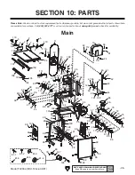
REF PART #

DESCRIPTION

REF

PART #

DESCRIPTION

1

PT32304001

MEAT PUSHER

62

PT32304062

KEY 6 X 6 X 70

2

PT32304002

CAP SCREW M6-1 X 16

63

PT32304063

MEAT GRINDER SPINDLE

3

PT32304003

PUSHER SHAFT 248MM

64

PT32304064

ROLL PIN 4 X 40

4

PT32304004

SHAFT SUPPORT BRACKET

65

PT32304065

BALL BEARING 6203ZZ

5

PT32304005

KNOB BOLT M6-1 X 20, 8-LOBE, D30

66

PT32304066

MEAT GRINDER MOUNTING BRACKET

6

PT32304006

TABLE 23-1/2" X 18-1/4"

67

PT32304067

FOLDING HANDLE 11 X 74, M10-1.5 X 18

7

PT32304007

FENCE

68

PT32304068

HOPPER FUNNEL

8

PT32304008

FENCE SHAFT 305MM

69

PT32304069

BUSHING 22.5ID X 35OD X 15L

9

PT32304009

EXT RETAINING RING 14MM

70

PT32304070

AUGER

10

PT32304010

BALL BEARING 6202RS

71

PT32304071

AUGER SCREW M8-1.25 X 29

11

PT32304011

BLADE 5/8" X 82" 4 TPI

72

PT32304072

REAMER

12

PT32304012

UPPER WHEEL 10"

73

PT32304073

GRINDING PLATE 3/16"

13

PT32304013

INT RETAINING RING 38MM

74

PT32304074

LOCKING COLLAR

14

PT32304014

WHEEL SHAFT M12-1.75 X 43

75

PT32304075

COLLAR GASKET 3.25 X 63.5 X 70

15

PT32304015

WHEEL COVER

76

PT32304076

SAUSAGE STUFFER

16

PT32304016

HEX NUT M10-1.5

77

PT32304077

LOCK WASHER 8MM

17

PT32304017

FLAT WASHER 10MM

78

PT32304078

STAND TOP

18

PT32304018

COMPRESSION SPRING 4 X 18.5 X 42

79

PT32304079

SET SCREW M8-1.25 X 12

19

PT32304019

TENSION PLATE

80

PT32304080

MOTOR PULLEY

20

PT32304020

TRACKING PLATE

81

PT32304081

MOTOR 3/4 HP 120V 1-PH

21

PT32304021

DOWEL PIN 8 X 50

81-1 PT32304081-1 R CAPACITOR 35M 250V 1-1/2 X 2-7/8

22

PT32304022

RETENTION BRACKET

81-2 PT32304081-2 BALL BEARING 6203ZZ

23

PT32304023

ROLLER BRACKET

81-3 PT32304081-3 MOTOR FAN

24

PT32304024

CAP SCREW M6-1 X 10

81-4 PT32304081-4 FAN COVER

25

PT32304025

ROLLER AXLE 10 X 34MM

81-5 PT32304081-5 MOTOR JUNCTION BOX

26

PT32304026

ROLLER 10 X 33MM

81-6 PT32304081-6 STRAIN RELIEF TYPE-3 M18-2.5

27

PT32304027

REAR COVER

82

PT32304082

MOTOR MOUNT

28

PT32304028

HEX NUT M8-1.25

83

PT32304083

UPPER BRACE

29

PT32304029

FLAT WASHER 8MM

84

PT32304084

SWITCH HOUSING

30

PT32304030

CAP SCREW M6-1 X 10

85

PT32304085

ON/OFF SWITCH GAOYOU KJD6 250V

31

PT32304031

LOWER BLADE GUIDE

86

PT32304086

MEAT GRINDER COVER

32

PT32304032

LOWER GUIDE SUPPORT BRACKET

87

PT32304087

PHLP HD SCR M4-.7 X 6

33

PT32304033

BALL BEARING 608-2RS

88

PT32304088

CABLE BOOT 8 X 18MM

34

PT32304034

CAP SCREW M8-1.25 X 25

89

PT32304089

POWER CORD 14G 3W 72" 5-15P

35

PT32304035

SAW BODY

90

PT32304090

LOCK WASHER 4MM

36

PT32304036

SET SCREW M8-1.25 X 16

91

PT32304091

TERMINAL LUG 18AWG

37

PT32304037

HEX NUT M6-1

92

PT32304092

EXT TOOTH WASHER 4MM

38

PT32304038

COLUMN COVER

93

PT32304093

CARRIAGE BOLT M8-1.25 X 16

39

PT32304039

FLAT WASHER 6MM

94

PT32304094

FLAT WASHER 12MM

40

PT32304040

HEX BOLT M8-1.25 X 12

95

PT32304095

SIDE BRACE

41

PT32304041

GUIDE RAIL SUPPORT BRACKET

96

PT32304096

STAND COVER

42

PT32304042

CAP SCREW M4-.7 X 10

97

PT32304097

ROLL PIN 3 X 16

43

PT32304043

BLADE GUIDE RAIL

98

PT32304098

TAP SCREW M2.2 X 12

44

PT32304044

BLADE GUIDE SUPPORT BRACKET

99

PT32304099

STAND LEG

45

PT32304045

SUPPORT BEARING PIN 10 X 34MM

100

PT32304100

STUD-SE M10-1.5 X 104, 54

46

PT32304046

BALL BEARING 6200-2RS

101

PT32304101

TAP SCREW M4.2 X 13

47

PT32304047

EXT RETAINING RING 10MM

102

PT32304102

RUBBER FOOT

48

PT32304048

BLADE GUIDE BRACKET

103

PT32304103

HEX BOLT M6-1 X 20

49

PT32304049

BLADE GUIDE

104

PT32304104

HEX NUT M5-.8

50

PT32304050

BLADE GUARD

105

PT32304105

LOCK WASHER 5MM

51

PT32304051

HEX NUT M12-1.75

106

PT32304106

FLAT WASHER 5MM

52

PT32304052

LOCK WASHER 12MM

107

PT32304107

TABLE SLIDE RAIL (LEFT)

53

PT32304053

BALL BEARING 6005ZZ

108

PT32304108

TABLE SUPPORT BEAM

54

PT32304054

WHEEL PULLEY

109

PT32304109

TABLE SLIDE RAIL (RIGHT)

55

PT32304055

V-BELT A-1000

110

PT32304110

SHAFT HANDLE

56

PT32304056

LOWER WHEEL 10"

111

PT32304111

PULLEY GUARD

57

PT32304057

HEX BOLT M6-1 X 25

112

PT32304112

FLAT WASHER 4MM

58

PT32304058

WHEEL SUPPORT PLATE

113

PT32304113

SWITCH COVER, FRONT

59

PT32304059

BUSHING 19.5ID X 27OD X 30L

114

PT32304114

COVER SEAL

60

PT32304060

BUSHING 19ID X 28.5OD X 30.5L

115

PT32304115

TERMINAL BLOCK PA10-2P

61

PT32304061

HEX BOLT M8-1.25 X 20

116

PT32304116

TAP SCREW M2.9 X 20

-46-

Model T32304 (Mfd. Since 02/21)

Main Parts List

Содержание T32304

Страница 1: ...MANUAL For models manufactured since 02 21 COPYRIGHT APRIL 2021 BY GRIZZLY INDUSTRIAL INC WARNING NO PORTION OF THIS MANUAL MAY BE REPRODUCED IN ANY SHAPE OR FORM WITHOUT THE WRITTEN APPROVAL OF GRIZZ...

Страница 2: ...g grinding tool integrity and the usage of personal protective equipment The manufacturer will not be held liable for injury or property damage from negligence improper training machine modifications...

Страница 3: ...nts 4 Machine Data Sheet 5 SECTION 1 SAFETY 7 Safety Instructions for Machinery 7 Additional Safety for Meat Saws 9 SECTION 2 POWER SUPPLY 10 SECTION 3 SETUP 12 Needed for Setup 12 Unpacking 12 Invent...

Страница 4: ...h the instruc tions specifications drawings and photographs in this manual Sometimes we make mistakes but our policy of continuous improvement also means that sometimes the machine you receive is slig...

Страница 5: ...ring operation Model T32304 Mfd Since 02 21 3 Identification Become familiar with the names and locations of the controls and features shown below to better understand the instructions in this manual...

Страница 6: ...and adjusts to desired width of cut F Blade Guide Assembly Uses blade guides and a support bearing to help keep blade straight while cutting Can be adjusted up or down depending on workpiece height G...

Страница 7: ...117 lbs Length x Width x Height 39 x 20 x 25 in Must Ship Upright Yes Electrical Power Requirement 120V Single Phase 60 Hz Full Load Current Rating 4 6A Minimum Circuit Size 15A Connection Type Cord P...

Страница 8: ...l Fence Aluminum Base Stand Steel Frame Body Steel Wheels Aluminum Wheel Cover Steel Paint Type Finish Powder Coated Other Related Information Wheel Diameter 10 in Wheel Width 1 in Other Specification...

Страница 9: ...Do not use machinery in areas that are wet cluttered or have poor lighting Operating machinery in these areas greatly increases the risk of accidents and injury MENTAL ALERTNESS REQUIRED Full mental a...

Страница 10: ...ake sure they are properly installed undamaged and working correctly BEFORE operating machine FORCING MACHINERY Do not force machine It will do the job safer and better at the rate for which it was de...

Страница 11: ...This could result in blade damage or breakage WORKPIECE MATERIAL This machine is designed to cut fresh and frozen meat and bones This machine is NOT designed to cut wood metal glass stone tile etc HA...

Страница 12: ...ower supply circuit that meets the specified circuit requirements This machine is prewired to operate on a power supply circuit that has a verified ground and meets the following requirements Serious...

Страница 13: ...he risk of electric shock by providing a path of least resistance for electric current This machine is equipped with a power cord that has an equipment grounding wire and a grounding plug Only insert...

Страница 14: ...eather gloves when handling saw blades This machine presents serious injury hazards to untrained users Read through this entire manu al to become familiar with the controls and opera tions before star...

Страница 15: ...re 6 Stand and motor inventory Figure 7 Table and hardware inventory Model T32304 Mfd Since 02 21 13 Inventory Box 1 Figures 5 7 Qty A Model T32304 Saw Body 1 B Stand Legs 2 C Stand Top 1 D Upper Brac...

Страница 16: ...Hardware Recognition Chart USE THIS CHART TO MATCH UP HARDWARE DURING THE INVENTORY AND ASSEMBLY PROCESS 5mm 5mm Flat Head Cap Screw 14 Model T32304 Mfd Since 02 21...

Страница 17: ...machine components For best results operate this machine in a dry environment that is free from excessive moisture hazardous chemi cals airborne abrasives or extreme conditions Extreme conditions for...

Страница 18: ...flat washers and M8 1 25 hex nuts IMPORTANT Verify clamp hole on motor mount is positioned on top see Figure 12 before proceeding to the next step Assembly To assemble machine 1 Insert 4 M6 1 x 20 he...

Страница 19: ...7 With help from an assistant lift saw body and place on stand see Figure 14 Secure with 3 M8 1 25 x 20 hex bolts 8mm flat washers and 8mm lock washers through elongated holes on stand top 8 Fit V bel...

Страница 20: ...e parallel and coplanar straightedge will touch the top and bottom rims on both pulleys No further adjust ment is required If pulleys are parallel but not coplanar straightedge will touch the top and...

Страница 21: ...le lock is spring loaded and will engage with hole in table rail to prevent table from sliding 15 Attach retention bracket underneath open end of table and secure with 4 M6 1 x 10 cap screws see Figur...

Страница 22: ...tighten lock handle to secure meat grinder in place see Figure 26 Note If meat grinder does not fully seat it may be necessary to spin pulley wheel by hand so meat grinder tongue fits into groove on a...

Страница 23: ...d the orientation of the wheels in relation to each other determine how the blade tracks IMPORTANT Improper tracking reduces cutting accuracy causes excess vibrations and places stress on the blade an...

Страница 24: ...loosen screws to adjust pitch tilt of upper wheel Note Pitch control screws control left and right pitch and tilt control screw controls up and down tilt of the wheel 5 While adjusting screws rotate...

Страница 25: ...d safety components are functioning correctly If you find an unusual problem during the test run immediately stop the machine disconnect it from power and fix the problem BEFORE operating the machine...

Страница 26: ...n Grizzly Industrial will not be held liable for accidents caused by lack of training To reduce risk of eye or face injury from flying debris always wear safety glasses and face shield when oper ating...

Страница 27: ...nsion properly adjusted blade guides and other bandsaw compo nents and using an appropriate feed rate Improper blade tension is unsafe produces inac curate and inconsistent results and introduces unne...

Страница 28: ...e to increase blade tension and counterclockwise to decrease blade tension Blade Tension Nut 5 Install upper wheel cover and secure Adjusting Blade Support Bearings Support bearings are positioned beh...

Страница 29: ...lade is tracking and ten sioned correctly before performing this procedure see Tensioning Blade on Page 25 Tools Needed Qty Hex Wrench 5mm 1 To adjust blade guides 1 DISCONNECT MACHINE FROM POWER 2 Re...

Страница 30: ...d when removing table 7 Loosen lower blade guide adjustment screws see Figure 39 adjust blade guides to approximately 0 004 about the thickness of a dollar bill away from blade 8 Position blade guides...

Страница 31: ...el T32304 is a general purpose 4 TPI Teeth Per Inch blade Under normal conditions the saw blade should be replaced after cutting approximately 4400 lbs of meat or bone Do research to help select the b...

Страница 32: ...see Figure 45 counterclockwise until blade moves freely Blade Guide 1 of 2 8 Put on a pair of heavy leather gloves to pro tect your hands from blade teeth then care fully remove blade Blade Tension N...

Страница 33: ...et door re install covers and table see Figure 48 removed in Steps 2 3 of Removing Blade on Page 29 and secure Cutting Meat Bone The Model T32304 10 3 4 HP Meat Cutting Bandsaw is designed for cutting...

Страница 34: ...Page 33 3 Loosen lock handle on meat grinder and line up fixed key on grinder with keyway on grinder mount see Figure 49 4 Slide meat grinder all the way on grinder mount and tighten lock handle to s...

Страница 35: ...e manufacturer s recommendations To prevent illness or death never use a product that will make the meat unsafe for human consumption Figure 52 Table and meat grinder components disassembled Model T32...

Страница 36: ...at the same time because they use heat Place any parts that will fit inside of the dishwasher and use the highest possible heat settings minimum 171 F 77 C If it is an option use the dish washer to dr...

Страница 37: ...their growth Some sanitizers require direct applications while others are designed to be diluted in water and used to soak the item for a specified period of time The best method for choosing a chemic...

Страница 38: ...20502 T20503 T20456 H6572 Grease Resistant Mat 3 x 3 x 3 4 These Black Grease Resistant Mats are engi neered for proper back and leg support using super tough virgin rubber material The non slip surfa...

Страница 39: ...require no maintenance throughout their lifespan Schedule For optimum performance from this machine this maintenance schedule must be strictly followed Ongoing To minimize your risk of injury and mai...

Страница 40: ...switch clean contact points Replace either if at fault 6 Fix broken wires or disconnected corroded connections Page 43 7 Replace switch 8 Replace motor Machine stalls or is underpowered 1 Excessive fe...

Страница 41: ...guides support bearings Page 27 Replace if faulty 7 Clean and sanitize blade guides support bearings Page 33 Blade tracks incorrectly or comes off wheels 1 Blade tracking is incorrect 2 Blade tension...

Страница 42: ...lt 1 DISCONNECT MACHINE FROM POWER 2 Remove table and both stand covers then open cabinet door Note Fence and meat pusher can remain installed when removing table 3 Inspect V belt if it is cracked fra...

Страница 43: ...will touch the top and bottom rims on both pulleys No further adjust ment is required If pulleys are parallel but not coplanar straightedge will touch the top and bot tom rims on one pulley but will n...

Страница 44: ...y not match your machine If you find this to be the case use the wiring diagram inside the motor junction box CAPACITORS INVERTERS Some capacitors and power inverters store an electrical charge for up...

Страница 45: ...D6 Ground Ground Neutral Hot Ground 120VAC 5 15 Plug MOTOR JUNCTION BOX Run Capacitor 35 F 250VAC WARNING SHOCK HAZARD Disconnect power before working on wiring Model T32304 Mfd Since 02 21 43 READ EL...

Страница 46: ...Figure 61 Motor junction box 44 Model T32304 Mfd Since 02 21 READ ELECTRICAL SAFETY ON PAGE 42 Electrical Components...

Страница 47: ...5 26 27 28 28 28 29 30 31 32 33 34 35 36 37 37 38 39 39 39 39 40 41 42 42 42 43 44 45 46 47 47 48 49 50 51 52 53 54 55 56 57 58 59 60 61 61 61 62 63 64 65 66 67 68 69 70 71 72 73 74 75 76 77 77 77 78...

Страница 48: ...304084 SWITCH HOUSING 30 PT32304030 CAP SCREW M6 1 X 10 85 PT32304085 ON OFF SWITCH GAOYOU KJD6 250V 31 PT32304031 LOWER BLADE GUIDE 86 PT32304086 MEAT GRINDER COVER 32 PT32304032 LOWER GUIDE SUPPORT...

Страница 49: ...ROMMET 45 X 57 X 6MM 121 PT32304121 CAP SCREW M5 8 X 10 133 PT32304133 KNOB M5 8 D15 BALL 122 PT32304122 CAP SCREW M5 8 X 16 134 PT32304134 TABLE LOCK SUPPORT BRACKET 123 PT32304123 FRICTION PAD 135 P...

Страница 50: ...13 204 REF PART DESCRIPTION REF PART DESCRIPTION 200 PT32304200 TOUCH UP PAINT GLOSS BLACK 207 PT32304207 SAFETY GLASSES LABEL 201 PT32304201 TOUCH UP PAINT GRIZZLY GREEN 208 PT32304208 DOOR CLOSED LA...

Страница 51: ...ntal contingent special or consequential damages arising from the use of our products The manufacturers reserve the right to change specifications at any time because they constantly strive to achieve...

Страница 52: ......

Отзывы: