


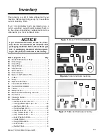


Figure 21. Retention bracket installed.
Figure 22. Location of fence and meat pusher
components (saw body removed for clarity).
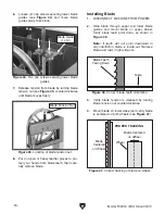
Figure 20. Example of aligning table with rollers
and table slot with blade.
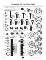
x 4
x 4
Model T32304 (Mfd. Since 02/21)
-19-
13. Look down underside of table, as shown in
Figure 20, and line up grooves in table rails
with rollers on saw body. Slide table on first
group of rollers and make sure blade fits into
slot in table.
14. Pull back on table lock to slide table over
second group of rollers.
Note: Table lock is spring-loaded and will
engage with hole in table rail to prevent table
from sliding.
15. Attach retention bracket underneath open
end of table and secure with (4) M6-1 x 10
cap screws (see
Figure 21).
Table Slot
Cap Screw
(1 of 4)
Retention
Bracket
16. Pull back on table lock and verify table slides
back and forth, then lock table.
17. Attach (2) support brackets to table using (4)
M6-1 x 16 cap screws (see
Figure 22).
18. Slide fence shaft through left support bracket,
then secure with (1) lock knob, as shown in
Figure 22.
19. Slide pusher shaft through right support
bracket, then secure with (1) lock knob (see
Figure 22).
Fence Shaft
Lock
Knob
(1 of 2)
Left
Support
Bracket
Pusher
Shaft
Cap Screw
(1 of 4)
Right
Support
Bracket
Содержание T32304
Страница 52: ......