


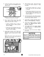


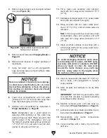


Figure 44. Two cap screws securing lower blade
guides.
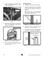
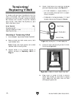
Figure 45. Location of blade tension nut.
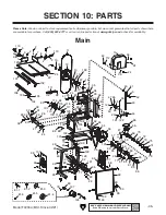
Blade Centered
on Wheel
Blade
Centered
on Wheel
PROPER TRACKING
Wheel
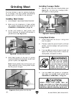
Figure 47. Correct tracking of blade on wheel.
Table
Blade Teeth
Facing Down
Figure 46. Correct blade teeth orientation.
-30-
Model T32304 (Mfd. Since 02/21)
6. Loosen (2) cap screws securing lower blade
guides (see
Figure 44) and move blade
guides away from blade.
7. Release tension from blade by turning blade
tension nut (see
Figure 45) counterclockwise
until blade moves freely.
Blade Guide
(1 of 2)
8. Put on a pair of heavy leather gloves to pro-
tect your hands from blade teeth, then care-
fully remove blade.
Blade Tension Nut
3. Verify blade tension is released by turning
blade tension nut counterclockwise.
4. Mount blade on lower wheel and verify blade
is centered on both wheels (see
Figure 47).
Installing Blade
1. DISCONNECT MACHINE FROM POWER!
2. Slide blade through upper and lower blade
guides and mount blade on upper wheel.
Verify blade teeth point down, as shown in
Figure 46.
Note: If teeth will not point downward in
any orientation, blade is inside-out. Remove
blade and twist it right-side-out.
Содержание T32304
Страница 52: ......