


-36-
Model T28366 (Mfd. Since 04/18)
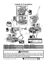
Adjusting Miter
Lock Lever
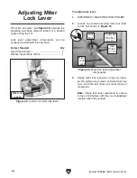
The miter lock lever (see
Figure 49) ensures the
swiveling saw base remains locked at a desired
angle during the cut.
Lock lever adjustment components can be
accessed underneath the saw base.
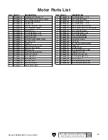
Item(s)
Needed
Qty
Hex Wrench 6mm .............................................. 1
Wrench Open-Ends 14mm ................................ 1
3. Rotate miter lock lever left or right, as need-
ed. Re-tighten cap screws and tensioner hex
nuts, and then test miter lock lever range of
movement.
Note: Check lock lever clearance to ensure
it does not interfere with the vise handwheel
rotation when fully locked.
To adjust lock lever:
1. DISCONNECT MACHINE FROM POWER!
2. Loosen cap screws securing miter lock lever
to lock bolt shown in
Figure 50.
Figure 50. Miter lock lever adjustment
components.
Lock
Bolt
Tensioner
Hex Nut
(1 of 3)
Cap
Screw
(1 of 3)
Figure 49. Location of miter lock lever.
Miter Lock
Lever
Miter
Lock
Lever