


-16-
Model T28366 (Mfd. Since 04/18)
Note: Gearbox is pre-filled with oil.
Assembly
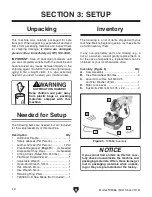
5. Verify there is oil in gearbox by lower-
ing headstock and allowing oil to settle
for 10 seconds, then check oil sight glass
(see
Figure 16). Oil level should be halfway
up sight glass, near red indicator dot.
To assemble machine:
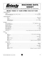
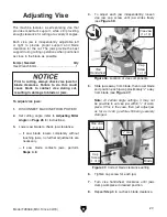
1. Thread (4) vise handwheel handles into
handwheel hub (see
Figure 13).
The machine must be fully assembled before it
can be operated. Before beginning the assembly
process, refer to
Needed for Setup and gather
all listed items. To ensure the assembly process
goes smoothly, first clean any parts that are cov-
ered or coated in heavy-duty rust preventative (if
applicable).
— If oil level is not halfway up sight glass,
refer to
Gearbox Oil on Page 32.
— If oil level is at least halfway up sight glass,
no further action is required. Continue to
Step 6.
Figure 16. Location of oil sight glass.
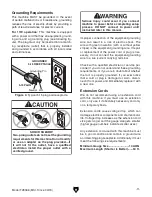
Figure 15. Lever arm and trigger button cord
installed.
3. Thread lever arm into headstock as far as
it goes, then back it off less than a full turn
to position it so start button cord is on top of
lever arm, as shown in
Figure 15, then tight-
en hex nut to secure lever arm.
4. Connect start button cord to control box
(see
Figure 15).
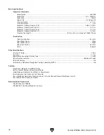
2. Remove temporary gearbox oil plug (see
Figure 14) from lever arm mounting hole
and reverse positions of M22-2.5 hex nut
and 22mm flat washer on lever arm. (Washer
secured on lever arm for shipping purposes
only.)
Figure 14. Location of temporary plug.
Temporary
Plug
Oil
Sight
Glass
Start
Button
Cord
Lever
Arm
Figure 13. Vise handwheel handles threaded
into handwheel hub.
Handwheel
Hub
Vise Handwheel
Handles