background image

Model G1014Z/G1014ZX (Mfd. Since 08/22)

-7-

The information contained herein is deemed accurate as of 8/17/2022 and represents our most recent product specifications.

Due to our ongoing improvement efforts, this information may not accurately describe items previously purchased.

PAGE 1 OF 2

Model G1014ZX

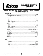
MACHINE DATA

SHEET

Customer Service #: (570) 546-9663 · To Order Call: (800) 523-4777 · Fax #: (800) 438-5901

MODEL G1014ZX 6" X 48" BELT/9" DISC COMBO SANDER

WITH CABINET STAND

Product Dimensions:

Weight.............................................................................................................................................................. 148 lbs.

Width (side-to-side) x Depth (front-to-back) x Height........................................................................... 30 x 24 x 56 in.

Footprint (Length x Width)..................................................................................................................... 15 x 16-1/2 in.

Shipping Dimensions:

Carton #1

Type........................................................................................................................................... Cardboard Box

Content................................................................................................................................................. Machine

Weight.................................................................................................................................................... 106 lbs.

Length x Width x Height............................................................................................................. 29 x 19 x 15 in.

Must Ship Upright.......................................................................................................................................... No

Carton #2

Type........................................................................................................................................... Cardboard Box

Content...................................................................................................................................................... Stand

Weight...................................................................................................................................................... 52 lbs.

Length x Width x Height............................................................................................................. 17 x 20 x 28 in.

Must Ship Upright.......................................................................................................................................... No

Electrical:

Power Requirement............................................................................................. 110V or 220V, Single-Phase, 60 Hz

Prewired Voltage.................................................................................................................................................. 110V

Full-Load Current Rating....................................................................................................... 12A at 110V, 6A at 220V

Minimum Circuit Size.......................................................................................................... 15A at 110V, 15A at 220V

Connection Type....................................................................................................................................... Cord & Plug

Power Cord Included.............................................................................................................................................. Yes

Power Cord Length.......................................................................................................................................... 8-1/2 ft.

Power Cord Gauge......................................................................................................................................... 16 AWG

Plug Included.......................................................................................................................................................... Yes

Included Plug Type................................................................................................................................. 5-15 for 110V

Recommended Plug Type...................................................................................................................... 6-15 for 220V

Switch Type.................................................................................................. Paddle Safety Switch w/Removable Key

Motors:

Main

Horsepower............................................................................................................................................. 3/4 HP

Phase............................................................................................................................................ Single-Phase

Amps....................................................................................................................................................... 12A/6A

Speed................................................................................................................................................ 3450 RPM

Type................................................................................................................. TEFC Capacitor-Start Induction

Power Transfer ............................................................................................................................................ Belt

Bearings........................................................................................................ Sealed & Permanently Lubricated

Centrifugal Switch/Contacts Type......................................................................................................... External

Содержание G1014Z

Страница 1: ...G NO PORTION OF THIS MANUAL MAY BE REPRODUCED IN ANY SHAPE OR FORM WITHOUT THE WRITTEN APPROVAL OF GRIZZLY INDUSTRIAL INC BL11448 PRINTED IN TAIWAN V3 08 22 MODEL G1014Z G1014ZX 6 X 48 BELT 9 DISC COM...

Страница 2: ...g grinding tool integrity and the usage of personal protective equipment The manufacturer will not be held liable for injury or property damage from negligence improper training machine modifications...

Страница 3: ...Tips 32 Choosing Sandpaper 32 Workpiece Inspection 33 Horizontal Edge Sanding 33 Contour Sanding 35 Disc Sanding 35 Vertical Sanding 36 Changing Sanding Belt 39 Adjusting Sanding Belt Tension 40 Track...

Страница 4: ...uld it be improved Please take a few minutes to give us feedback Grizzly Documentation Manager P O Box 2069 Bellingham WA 98227 2069 Email manuals grizzly com Contact Info We are proud to provide a hi...

Страница 5: ...ckback by sanding in accordance with directional arrows Miter Gauge 2 Dust Port Door Handle 21 2 Dust Port Tracking Knob Pulley Cover Angle Scale Lock Knob Support Rod Idler Roller Sanding Belt Drive...

Страница 6: ...e switch location on G1014ZX A B A B Table Controls Figure 3 Table tilt controls C Miter Gauge Moves workpieces into the sanding disc horizontal sanding or belt ver tical sanding at a specific angle S...

Страница 7: ...ctrical Power Requirement 110V or 220V Single Phase 60 Hz Prewired Voltage 110V Full Load Current Rating 12A at 110V 6A at 220V Minimum Circuit Size 15A at 110V 15A at 220V Connection Type Cord Plug P...

Страница 8: ...35 in Construction Materials Base Cast Iron Stand Preformed Steel Table Cast Iron Frame Cast Iron Disc Cast Iron Miter Gauge Die Cast Aluminum Aluminum Bar Paint Type Finish Epoxy Other Related Info...

Страница 9: ...Box Content Machine Weight 106 lbs Length x Width x Height 29 x 19 x 15 in Must Ship Upright No Carton 2 Type Cardboard Box Content Stand Weight 52 lbs Length x Width x Height 17 x 20 x 28 in Must Sh...

Страница 10: ...Info Disc Diameter 9 in Disc Speed 2420 RPM Disc Sandpaper Backing Type PSA Table Length 12 1 4 in Table Width 6 in Table Thickness 1 in Table Tilt Left 0 Right 45 deg Table to Floor Height 37 1 2 in...

Страница 11: ...p kid proof DANGEROUS ENVIRONMENTS Do not use machinery in areas that are wet cluttered or have poor lighting Operating machinery in these areas greatly increases the risk of accidents and injury MENT...

Страница 12: ...with moving parts or flying debris Make sure they are properly installed undamaged and working correctly BEFORE operating machine FORCING MACHINERY Do not force machine It will do the job safer and be...

Страница 13: ...k pieces can result in loss of control resulting in abrasion injuries impact injuries or damage to sandpaper Only sand solid workpieces that can withstand power sanding forces Make sure work piece sha...

Страница 14: ...operation and make sure it is connected to a power supply circuit that meets the specified circuit requirements For your own safety and protection of property consult an electrician if you are unsure...

Страница 15: ...he following size requirements Minimum Gauge Size 14 AWG Maximum Length Shorter is Better 50 ft Grounding Requirements This machine MUST be grounded In the event of certain malfunctions or breakdowns...

Страница 16: ...Wires with Wire Nuts Figure 7 Motor prewired for 110V The voltage conversion MUST be performed by an electrician or qualified service personnel The voltage conversion procedure consists of rewiring th...

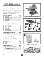
Страница 17: ...operator injury If normal safety pre cautions are overlooked or ignored seri ous personal injury may occur The following items are needed but not included for the setup assembly of this machine This m...

Страница 18: ...16 Model G1014Z G1014ZX Mfd Since 08 22 5mm Hardware Recognition Chart...

Страница 19: ...x 3 8 21 2 Dust Port 4 Hex Nuts 10 24 21 2 Dust Port 4 Flat Washers 10 21 2 Dust Port 4 Hex Nuts 3 8 16 Quick Release Lever 2 Thumb Knobs 1 4 20 x 1 2 Sander Unit 2 Flat Washers 1 4 Sander Unit 2 Thu...

Страница 20: ...1 Hardware not shown Qty Hex Nuts 5 16 18 Cabinet 4 Hex Bolts 5 16 18 x 1 Cabinet 4 Flat Washers 5 16 Cabinet 4 Thumb Knobs 1 4 20 x 1 2 Sander Unit 2 Flat Washers 1 4 Sander Unit 2 Thumb Knobs M5 8 x...

Страница 21: ...o a thorough job cleaning your machine The time you spend doing this now will give you a better appreciation for the proper care of your machine s unpainted surfaces There are many ways to remove this...

Страница 22: ...If not required by any local codes fastening the machine to the floor is an optional step If you choose not to do this with your machine we rec ommend placing it on machine mounts as these provide an...

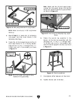
Страница 23: ...9 Short upper and lower braces fastened to leg assembly Short Lower Brace x 8 Short Upper Braces Figure 21 Stand assembled 7 Final tighten all the fasteners on the stand 8 Tighten the hex nuts on the...

Страница 24: ...eed to Step 16 11 Place the cabinet flat on its side on a flat protected surface but do not lay it down on the switch or door handle 16 With the help of an assistant lift the sanding unit onto the sta...

Страница 25: ...the roller adjustment bars see Figure 27 19 Install 1 1 4 20 x 1 2 thumb knob and 1 1 4 flat washer onto each side of sander behind idler roller see Figure 27 21 Align the keyway on the plate with the...

Страница 26: ...nsitive adhesive sanding disc make sure the cast iron plate is clean and install the sanding disc onto the plate as shown in Figure 32 Make sure the sanding disc adheres completely flat against the pl...

Страница 27: ...sand ing disc on both sides see Figure 37 then tighten the set screws on the work table arm Figure 37 Correct distance between disc and work table 1 16 Gap If the gap between the work table and the s...

Страница 28: ...hen tighten the hex nuts see Figure 39 Figure 39 Quick release lever installed Handle Rocker Arm Short Lever Arm 6 Stud Hex Nuts 36 Move the quick release lever toward the motor slide the sanding belt...

Страница 29: ...cated in the Test Run section on Page 30 1 4 1 2 Figure 43 Motor cord connected to power cord Power Cord Motor Cord 43 To set up the sanding belt in the vertical posi tion follow the instructions on P...

Страница 30: ...n the miter gauge and adjust it flush with the edge of the square 48 Tighten the lock knob and verify the setting Note Sometimes the tightening procedure can affect the adjustment 49 Loosen the screw...

Страница 31: ...must consider these variables 1 CFM rating of the dust collector 2 hose type and length between the dust col lector and the machine 3 number of branches or wyes and 4 amount of other open lines throu...

Страница 32: ...ch key from paddle switch Moving sanding belts are dangerously abra sive Use extreme caution when working near sanding surfaces To test run the machine 1 Clear all setup tools away from machine 2 Tie...

Страница 33: ...Secures any loose clothing removes loose jewelry and ties back long hair 5 Puts on some safety glasses and a respira tor Takes all other required safety precau tions 6 Starts the dust collector then...

Страница 34: ...an cause serious personal injury if it comes in contact with your fingers hands or other body parts Always support the workpiece against the table back stop or miter gauge when sanding Use extreme car...

Страница 35: ...y fine dust inherently created by all types of sanding operations even if a dust collector is used Additionally life of machine and sanding belts discs will be greatly reduced or immediately damaged f...

Страница 36: ...detail 5 Install the back stop so it is square with and 1 16 above the sanding belt see Figure 44 on Page 27 Figure 53 Table tilted to horizontal position Rotation Nut Hidden Sanding Disc Cover Rotat...

Страница 37: ...NECT MACHINE FROM POWER 2 Adjust the angles of the work table and the miter gauge for your operation 3 Connect the sander to power turn it ON and allow it to reach full speed 4 Place the workpiece on...

Страница 38: ...for Vertical Sanding If the sander is already in the vertical position skip to Performing Vertical Sanding on Page 38 Figure 61 Location of top rotation lock nut Top Rotation Nut Figure 62 Location o...

Страница 39: ...led for vertical sanding Mounting Bracket Set Screws 9 Adjust the front of the work table 1 16 away from the sanding belt see Figure 65 across its entire length If the gap is not 1 16 across the entir...

Страница 40: ...k on the scale then tighten the screw 12 Insert the miter gauge into the left side of the miter slot 1 Adjust the angles of the work table and miter gauge for your operation 2 Place the workpiece on t...

Страница 41: ...e idler and drive rollers making sure the arrows on the bottom of the belt face the front of the sander as shown in Figure 72 Figure 72 Installing new sanding belt Arrow Direction on Belt 6 Position t...

Страница 42: ...sion lever toward the motor to tighten the sanding belt 4 Push the belt in the center with your finger using moderate pressure The deflection is correct when the belt deflects 1 2 as shown in Figure 7...

Страница 43: ...l knob see Figure 77 carefully adjust the tracking in or out until the sanding belt is centered on the main roller see Figure 47 Page 28 Changing Sanding Disc The model G1014Z G1014ZX accepts 9 diamet...

Страница 44: ...s risk only install accessories recommended for this machine by Grizzly NOTICE Refer to our website or latest catalog for additional recommended accessories 6 x 48 Aluminum Oxide Sanding Belts Our alu...

Страница 45: ...ray G2871 Boeshield T 9 12 Oz Spray H3788 G96 Gun Treatment 12 Oz Spray Figure 81 Recommended products for protect ing unpainted cast iron steel parts on machinery For optimum performance from this ma...

Страница 46: ...achine oil onto the shaft see Figure 82 Move the work table back and forth to distribute the oil Lubrication It is essential to clean the components before lubricating them because dust and chips buil...

Страница 47: ...wrong 5 Pulley slipping on shaft 6 Machine undersized for task 7 Motor overheated 8 Extension cord too long 9 Centrifugal switch contact points at fault 10 Motor or motor bearings at fault 1 Only san...

Страница 48: ...tensioned properly 1 Tension sanding belt Page 40 2 Reduce workpiece pressure 3 Inspect tension V belt Page 49 Belts discs clog quickly or excessive sanding belt disc replacement 1 Sanding wet stock...

Страница 49: ...set to 90 1 Table is not square to sanding belt disc 1 Calibrate table tilt this page Workpiece not sanded square when miter gauge is set to 90 1 Miter gauge body is not square to miter bar 1 Calibrat...

Страница 50: ...no adjust ments need to be made If the distance is not the same from side to side loosen the screws see Figure 66 on Page 37 that secure the work table arm to the work table and adjust the table so it...

Страница 51: ...nsion The belt is correctly tensioned when there is approximately 1 4 deflection when it is pushed with moderate pressure as shown in Figure 87 Pulley Deflection Pulley Figure 87 Checking belt tension...

Страница 52: ...e parallel and in the same plane as each other Tools Needed Qty Hex Wrench 4mm 1 Straightedge 12 1 Standard Screwdriver 1 To check and adjust pulley alignment 1 DISCONNECT MACHINE FROM POWER 2 Remove...

Страница 53: ...s current at the time of printing but may not match your machine If you find this to be the case use the wiring diagram inside the motor junction box CAPACITORS INVERTERS Some capacitors and power inv...

Страница 54: ...Hot Hot Ground Ground 6 15 PLUG As Recommended 5 15 PLUG Included G 220V 110V PADDLE SWITCH KEDU HY18 viewed from behind MOTOR Wired 220V Ground MOTOR Prewired 110V Ground Start Capacitor 200MFD 125VA...

Страница 55: ...t Hot Hot Ground Ground 6 15 PLUG As Recommended 5 15 PLUG Included G 220V 110V MOTOR Wired 220V Ground MOTOR Prewired 110V Ground Start Capacitor 200MFD 125VAC Wired 220V Wired 220V Ground PADDLE SWI...

Страница 56: ...A 64 8 62B 3 2 37 19 97 32 34 6 42 35 21 22 10 16A 36 42 43 41 97 91 92 84A 83A 86A 85A 105 82A 87A 89 106 10 96 52 117 12 56 57 27A 138 51 50 27A 53A 71 49 80 30 90 119 118 51 120 46 114A 114A 1 127...

Страница 57: ...5 P1014Z025 FLAT WASHER 1 4 92 P1014Z092 FLAT WASHER 3 8 26 P1014Z026 PHLP HD SCR 1 4 20 X 1 2 93 P1014Z093 WASHER PLATE 19 X 88 27 P1014Z027 PHLP HD SCR 10 24 X 3 8 94A P1014Z094A KNOB 3 8 24 27A P10...

Страница 58: ...ed outlet 4 Support workpiece with miter gauge backstop or worktable 5 Maintain 1 16 maximum clearance between table and sandpaper 6 Never touch moving sandpaper 7 Always sand in accordance with direc...

Страница 59: ...18 93 7 15 7 17 107108 100 96 11 17 1 2 3 4 9 13 39 94 98 103 95 12 99 116 115 70 41 13 40 102 115 116 81 106 59 3 2 101 89 88 64 8 62 3 2 37 19 97 32 34 6 42 35 22 77 21 10 36 42 43 41 97 91 92 84 8...

Страница 60: ...2 P1014ZX092 FLAT WASHER 3 8 24 P1014ZX024 TRUNNION 93 P1014ZX093 WASHER PLATE 19 X 88 25 P1014ZX025 FLAT WASHER 1 4 94 P1014ZX094 KNOB 3 8 24 26 P1014ZX026 PHLP HD SCR 1 4 20 X 1 2 95 P1014ZX095 LOCK...

Страница 61: ...2 HEX BOLT 5 16 18 X 1 2 72 P1014ZX072 MOTOR CORD 1 FEMALE 41 P1014ZX041 HEX BOLT 5 16 18 X 1 72 1 P1014ZX072 1 MOTOR CORD 2 MALE 46 P1014ZX046 FLAT WASHER 10 73 P1014ZX073 CABINET 47 P1014ZX047 FLANG...

Страница 62: ...rotation and never force workpiece into sanding surface 10 Only remove jammed pieces when sandpaper is stopped 11 Turn motor OFF and disconnect power before changing sandpaper making adjustments or s...

Страница 63: ...rty or for incidental contingent special or consequential damages arising from the use of our products The manufacturers reserve the right to change specifications at any time because they constantly...

Страница 64: ......
Отзывы: