Model G1014Z/G1014ZX (Mfd. Since 08/22)
-37-
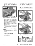
6. Raise the sanding belt frame until it reaches
the 90º mark (or the desired angle) on the tilt
scale, as shown in
Figure 63, then tighten
the rotation lock nuts.
Figure 63. Sanding belt tilted to 90º position.
7. Loosen the set screws that secure the table
support rod under the sanding disc, then
remove the support rod and work table
assembly.
8. Loosen the set screws on the mounting
bracket behind the motor, then slide the sup-
port rod and work table assembly into the
bracket hole, as shown in
Figure 64.
Figure 64. Work table installed for vertical
sanding.
Mounting
Bracket
Set Screws
9. Adjust the front of the work table
1
⁄
16
" away
from the sanding belt (see
Figure 65) across
its entire length.
— If the gap is not
1
⁄
16
" across the entire
length of the work table, loosen one or
both of the screws under the table (see
Figure 66), where the arm is attached to
the table, and adjust the table until the dis-
tance is correct, then tighten the screws.
Figure 65. Correct distance between work table
and sanding belt.
1
⁄
16
"
Gap
Note:
To reduce the chance of vibration or
rattling sounds, make sure the table support
rod does not touch the motor.
10. Tighten the mounting bracket set screws to
secure the support rod.
Figure 66. Location of work table arm mounting
screws.
Mounting
Screws
Arm
Angle
Pointer
Table Tilt
Knob
Содержание G1014Z
Страница 18: ...16 Model G1014Z G1014ZX Mfd Since 08 22 5mm Hardware Recognition Chart...
Страница 64: ......


