


Model G1014Z/G1014ZX (Mfd. Since 08/22)
-25-
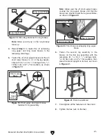
28. Loosen the (2) set screws on the work table
arm so their ends are flush with the inside of
the opening, as shown in
Figure 35.
29. Loosen the angle adjustment knob on the
work table (see
Figure 35), tilt the table to the
0º mark, then tighten the knob.
Figure 36. Installing work table onto table
support rod.
Figure 35. Location of work table installation
components.
Work
Table
Arm
Table Mount
Bracket Screw
Set
Screws
Angle
Adjustment
Knob
Opening
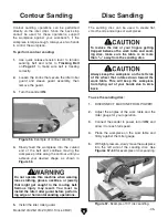
31. Using a ruler, adjust the edge of the work
table approximately
1
⁄
16
" away from the sand-
ing disc on both sides (see
Figure 37), then
tighten the set screws on the work table arm.
Figure 37. Correct distance between disc and
work table.
1
⁄
16
"
Gap
— If the gap between the work table and
the sanding disc is not the same on both
sides, loosen one of the table mount
bracket screws (see
Figure 35), adjust
the table as needed to even the gap, then
tighten the screw.
30. Slide the work table arm onto the table sup-
port rod, making sure that the set screws on
the table arm face the flat part of the rod, as
shown in
Figure 36.
To reduce the risk of your fingers getting
stuck between the work table and sanding
disc, set the table no more than
1
⁄
16
" away
from the sanding disc.
32. Square the table to the sanding disc (refer to
instructions on
Page 47 for more details).
Содержание G1014Z
Страница 18: ...16 Model G1014Z G1014ZX Mfd Since 08 22 5mm Hardware Recognition Chart...
Страница 64: ......